X ray differential phase contrast microscopic imaging system and imaging method

A technique of differential phase contrast and microscopic imaging, which is applied in material analysis using radiation, material analysis using radiation diffraction, material analysis using wave/particle radiation, etc. It can solve the difficulty of sample density distribution, limited application range, and inability Separating the contribution of absorption and attenuation light intensity, etc., to achieve the effect of easy promotion, simple operation and simple structure

Active Publication Date: 2013-10-23
INST OF HIGH ENERGY PHYSICS CHINESE ACADEMY OF SCI
View PDF4 Cites 17 Cited by
  • Summary
  • Abstract
  • Description
  • Claims
  • Application Information

AI Technical Summary

Problems solved by technology

However, the disadvantage of Zernike phase-contrast imaging is that its application range is limited to weak-phase samples with negligible absorption. When the absorption cannot be ignored, it cannot separate the respective contributions of absorption attenuation and phase shift to the light ...

Method used


Image

  • X ray differential phase contrast microscopic imaging system and imaging method
  • X ray differential phase contrast microscopic imaging system and imaging method
  • X ray differential phase contrast microscopic imaging system and imaging method

Examples


Embodiment Construction

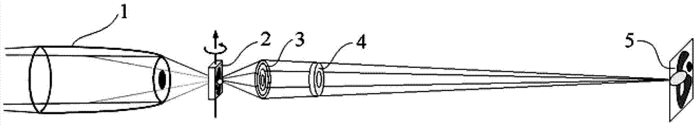
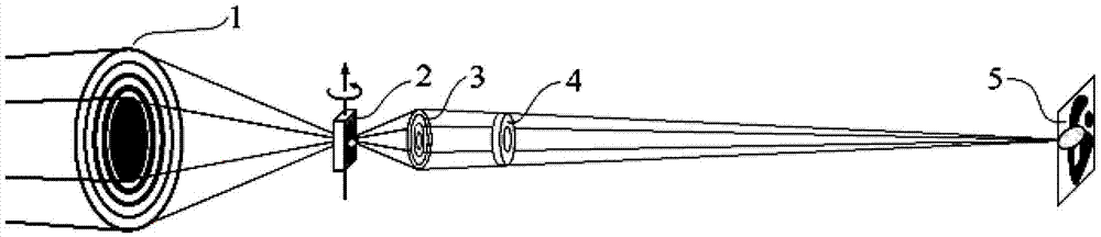
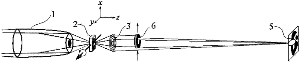
[0049] The X-ray differential phase-contrast microscopic imaging system of this embodiment includes a light source for generating X-rays, and also includes a condenser lens, a sample stage, an objective lens, an absorption ring, and an imaging detector arranged in sequence along the X-ray propagation direction.

[0050] Optionally, the X-ray light source is a monochromatic X-ray light source.

[0051] Optionally, the condenser is an ellipsoidal capillary, a tapered capillary or a focusing zone plate, and the central part of the ellipsoidal capillary, tapered capillary or focusing zone plate is a blocking diaphragm.

[0052] Optionally, the absorption ring is an annular diaphragm located near the rear focal plane of the objective lens, and is used to filter the object light from the sample. The shape and size of the absorption ring are the same as the annular reflective surface or diffraction surface on the condenser when there is no sample. The ring image formed near the rear ...


PUM


Abstract

The invention relates to the technical field of nanometer resolution X ray wave zone plate microscopic imaging and specifically discloses an X ray differential phase contrast microscopic imaging system and an imaging method. The system sequentially comprises an X ray light source, a collecting lens, a sample stage, an X ray wave zone plate, an absorbing ring and an imaging detector along the X ray propagation direction. The X ray differential phase contrast microscopic imaging system is provided to overcome the defects of an X ray microscope taking a wave zone plate as an objective lens, and the X ray differential phase contrast microscopic imaging system and the two-dimensional and/or three-dimensional imaging method provided by the invention can be used for quickly imaging objects.

Description

[0001] This invention claims priority from the following patents: [0002] 1. The application number is 201210097696.5, the application date is 2012.04.01, and the invention name is a Chinese invention patent named "Lenticular shearing imaging device and imaging method". [0003] 2. The application number is 201210277502.X, the application date is 2012.08.06, and the invention name is "X-ray differential phase contrast microscopic imaging system and its microscopic imaging method". technical field [0004] The invention relates to the technical field of nano-resolution X-ray zone plate microscopic imaging, in particular to an X-ray differential phase-contrast microscopic imaging system, a two-dimensional imaging method and a three-dimensional imaging method. Background technique [0005] The effect of matter on X-rays can be represented by the refractive index, n=1-δ+iβ, where δ is the attenuation rate of the real part of the refractive index, and β is the absorption term. ...

Claims


Application Information

Patent Timeline
IPC IPC(8): G01N23/00G01N23/06G01N23/20
Inventor 朱佩平洪友丽张凯袁清习黄万霞吴自玉
Owner INST OF HIGH ENERGY PHYSICS CHINESE ACADEMY OF SCI
Why Eureka
Try Eureka