Focusing and leveling device and method

A focusing and leveling device and a focusing technology, which are applied to exposure devices, optics, instruments, etc. in the photo-plate making process, can solve problems such as light not passing through, chromatic aberration is difficult to control, and order interference measurement, so as to improve energy utilization rate, The effect of reduced processing and assembly requirements and large compensation range

Active Publication Date: 2013-10-23
SHANGHAI MICRO ELECTRONICS EQUIP (GRP) CO LTD
View PDF4 Cites 9 Cited by
  • Summary
  • Abstract
  • Description
  • Claims
  • Application Information

AI Technical Summary

Problems solved by technology

[0004] The publication date is January 9, 1996. Japanese patent JP5483056 provides a focusing and leveling device. The technical defects of this device are: first, when the bandwidth is relatively large, the blazed grating cannot be used, otherwise it will cause part of the light to pass through, and When the distance between the slits is relatively close, the crosstalk between the stages affects the measurement
Then, when the incident angle is greater than 80 degrees, when the right-angle prism is glued with the projection diaphragm, the chromatic aberration is difficult to control
Thirdly, in the process of optical-mechanical assembly and adjustment, there is no focusing mechanism, which puts forward higher requirements for assembly and processing
Finally, due to the influence of temperature and other environments, the best focal plane of the objective lens has drifted. If the focus and leveling are not corrected to its own zero plane, the center of the focus and leveling measurement point will not coincide with the exposure field of view of the objective lens, causing measurement Error (the difference between the actual Z, Rx, Ry of the current exposure field and the Z, Rx, Ry measured by focusing and leveling)

Method used


Image

  • Focusing and leveling device and method
  • Focusing and leveling device and method
  • Focusing and leveling device and method

Examples


Embodiment Construction

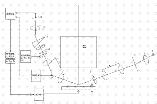
[0027] The focus measurement and control device and method for lithographic equipment of the present invention will be described in detail below in conjunction with the accompanying drawings. However, the present invention should be understood as not limited to such embodiments described below, and the technical idea of ​​the present invention can be implemented in combination with other known technologies or other technologies having the same functions as those known technologies.

[0028] In the following description, in order to clearly show the structure and working method of the present invention, many directional words will be used to describe, but "front", "rear", "left", "right", "outer", "inner" should be used Words such as ", "outward", "inward", "upper" and "lower" are to be understood as convenient terms, and should not be understood as restrictive terms. In addition, the term "Y direction" used in the following description mainly refers to the direction parallel t...


PUM


Abstract

The invention provides a focusing and leveling device which is used for the adjustment of a focal plane of a plane to be tested and the correction of a self zero plane. The focusing and leveling device comprises a light source module, an optical lens module, a tested object and a detector module, and is characterized in that the optical lens module comprises projection diaphragms, a focusing double-optical-wedge assembly, a projection optical assembly, a zero plane adjusting assembly and a detecting optical assembly, a light beam emitted from the light source module passes through the projection diaphragms, the projection optical assembly and first focusing double optical wedges, and then is reflected by the tested object so as to form a reflection light beam, and the reflection light beam sequentially passes through the projection optical assembly, the zero plane adjusting assembly and second focusing double optical wedges and then is received by the detector module. Meanwhile, the invention provides a focusing and leveling method.

Description

technical field [0001] The invention relates to the field of semiconductor integrated circuit equipment manufacturing, in particular to a focusing measurement and control device and method for photolithography equipment. Background technique [0002] Photolithography, or photolithography, has been widely used in integrated circuit manufacturing processes. This technology exposes through a photolithography system to transfer the designed mask pattern to the photoresist. Since the feature size of the integrated circuit is ultimately determined, the lithography system is an important device in the integrated circuit manufacturing process, and its precision requirements are self-evident for the lithography process. In order to obtain the best imaging effect, during exposure, the silicon wafer coated with photoresist is adsorbed on the film holder, and its upper surface needs to be placed at the optimum image plane height. [0003] In the projection exposure equipment, there mu...

Claims


Application Information

Patent Timeline
Patent Type & Authority Applications(China)
IPC IPC(8): G03F7/20G03F9/00
Inventor 卢丽荣李志丹张冲
Owner SHANGHAI MICRO ELECTRONICS EQUIP (GRP) CO LTD
Why Eureka
Try Eureka