Method for screening and correcting light intensity sampling points in alignment process

A sampling point, normal technology, applied in the direction of optics, microlithography exposure equipment, photoplate making process of pattern surface, etc., can solve the problem of affecting the precision, affecting the alignment speed of the lithography machine, the yield of the whole machine, and the light intensity The impact of radiation value and other issues, to ensure the correctness, to achieve the effect of silicon wafer alignment function

Active Publication Date: 2015-05-13
SHANGHAI MICRO ELECTRONICS EQUIP (GRP) CO LTD +1
View PDF5 Cites 0 Cited by
  • Summary
  • Abstract
  • Description
  • Claims
  • Application Information

AI Technical Summary

Problems solved by technology

In the existing dual-wavelength laser measurement system, due to the shaking of the workpiece table during the scanning process and the influence of the mark on the process conditions and other factors, it is easy to affect the light intensity radiation value obtained by the dual-wavelength laser measurement system irradiating the mark. It will lead to a deviation of a certain point or a section of the light intensity waveform, which will affect the calculation of the alignment accuracy, or even the failure of the silicon wafer alignment.
Ultimately affects the alignment speed of the lithography machine and the yield of the whole machine

Method used


Image

  • Method for screening and correcting light intensity sampling points in alignment process
  • Method for screening and correcting light intensity sampling points in alignment process
  • Method for screening and correcting light intensity sampling points in alignment process

Examples


Embodiment 1

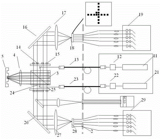
[0036] figure 1 Shown is a schematic diagram of a dual light source multi-level sub-alignment system of the known technology. Such as figure 1 As shown, the dual light source multi-level alignment system includes light source modules 11, 21, reference grating 2, optical fibers 13, 23, prisms 14, 24, polarizer 3, objective lens 4, marker 5, secondary wedges 15, 25, Mirrors 16 , 26 , objectives 17 , 27 , image planes 18 , 28 and detectors 19 , 29 . The specific working principle of the dual-light source multi-level alignment system is common knowledge to those skilled in the art, and will not be repeated here.

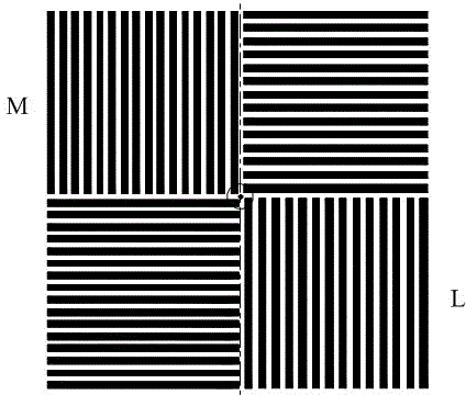
[0037] figure 2 The composition form of the alignment mark is shown, and the alignment system obtains the reflection information of various levels of light after the mark is irradiated. Issue the desired position of the mark, move the workpiece table, align the light source with the mark, and obtain the light intensity data I X (X=1, 2, 3….), calculate the alignme...

Embodiment 2

[0050] figure 1 Shown is a schematic diagram of a dual light source multi-level sub-alignment system of the known technology. Such as figure 1 As shown, the dual light source multi-level alignment system includes light source modules 11, 21, reference grating 2, optical fibers 13, 23, prisms 14, 24, polarizer 3, objective lens 4, marker 5, secondary wedges 15, 25, Mirrors 16 , 26 , objectives 17 , 27 , image planes 18 , 28 and detectors 19 , 29 . The specific working principle of the dual-light source multi-level alignment system is common knowledge to those skilled in the art, and will not be repeated here.

[0051] figure 2 The composition form of the alignment mark is shown, and the alignment system obtains the reflection information of various levels of light after the mark is irradiated.

[0052] Issue the desired position of the mark, move the workpiece table, align the light source with the mark, and obtain the light intensity data I X (X=1, 2, 3….), calculate the...

Embodiment 3

[0065] figure 1 Shown is a schematic diagram of a dual light source multi-level sub-alignment system of the known technology. Such as figure 1 As shown, the dual light source multi-level alignment system includes light source modules 11, 21, reference grating 2, optical fibers 13, 23, prisms 14, 24, polarizer 3, objective lens 4, marker 5, secondary wedges 15, 25, Mirrors 16 , 26 , objectives 17 , 27 , image planes 18 , 28 and detectors 19 , 29 . The specific working principle of the dual-light source multi-level alignment system is common knowledge to those skilled in the art, and will not be repeated here.

[0066] figure 2 The composition form of the alignment mark is shown. After the alignment system irradiates the mark, it obtains the reflection information of each level of light

[0067] Issue the desired position of the mark, move the workpiece table, align the light source with the mark, and obtain the light intensity data I X (X=1, 2, 3….), calculate the alignmen...


PUM


Abstract

The invention discloses a method for screening and correcting light intensity sampling points in an alignment process. The method comprises the steps of acquiring same sampling points in different periods in light intensity waveforms by contrasting and marking; judging whether the light intensity sampling points are distortional points according to the characteristics of different light intensity waveforms; judging whether the distortional points are continuous or not; and according to the continuity of the distortional points, correcting the distortional points to obtain corrected light intensity data.

Description

technical field [0001] The invention relates to the field of integrated circuit manufacturing equipment, in particular to a method for screening and correcting light intensity sampling points in an alignment process. Background technique [0002] The photolithography device is the main equipment for manufacturing integrated circuits. Its function is to sequentially image different mask patterns onto the precisely aligned positions on the substrate (silicon semiconductor wafer or LCD panel). However, this alignment position changes due to the physical and chemical changes experienced by successive patterns, so an alignment system is needed to ensure that the alignment position of the silicon wafer corresponding to the mask can be accurately aligned every time. As the number of electronic components per unit surface area of ​​the substrate increases and the size of electronic components becomes smaller and smaller, the precision requirements for integrated circuits are increas...

Claims


Application Information

Patent Timeline
Patent Type & Authority Patents(China)
IPC IPC(8): G03F7/20G03F9/00
Inventor 张磊韩悦赵新
Owner SHANGHAI MICRO ELECTRONICS EQUIP (GRP) CO LTD
Why Eureka
Try Eureka