
Semiconductor device

A semiconductor and component technology, applied in the field of semiconductor components, can solve the problems of charging circuit without design margin and high cost

Inactive Publication Date: 2013-10-23
KK TOSHIBA
View PDF6 Cites 0 Cited by
  • Summary
  • Abstract
  • Description
  • Claims
  • Application Information

AI Technical Summary

Problems solved by technology

[0005] However, if only resistors are used, there is a problem that current flows from the battery to the power supply side when the voltage applied to the battery becomes equal to or less than the rated voltage of the battery due to noise or the like.
There are problems such as there is no design margin for the charging circuit, and the cost is also increased.

Method used


Image

  • Semiconductor device
  • Semiconductor device
  • Semiconductor device

Examples


Embodiment Construction

[0017] Hereinafter, an embodiment will be described with reference to the drawings. In the drawings, the same symbols represent the same or similar parts.

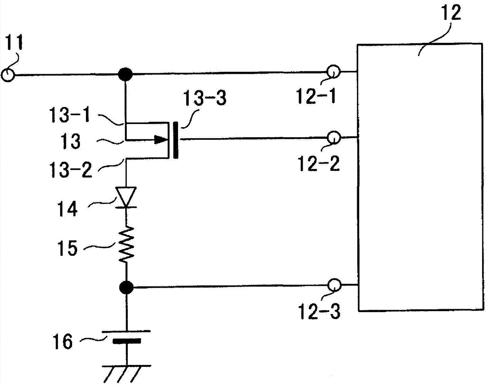
[0018] figure 1 A charging circuit of a mobile phone using the semiconductor element of this embodiment is shown. Such as figure 1 As shown, a DC voltage of 5 V from an AC adapter (not shown) is supplied to the input terminal 11 . This voltage is supplied to a charging voltage monitoring terminal 12 - 1 of the charging monitoring circuit 12 , and a part thereof is branched to be supplied to a source terminal 13 - 1 of a switching field effect transistor (hereinafter referred to as MOSFET) 13 .

[0019] A Schottky barrier diode (hereinafter referred to as SBD) 14 is connected in series to the drain terminal 13 - 2 of this MOSFET 13 . That is, the anode electrode side of the SBD 14 is connected to the drain terminal 13 - 2 of the MOSFET 13 , and the cathode electrode side of the SBD 14 is connected to the anode side of t...


PUM


Abstract

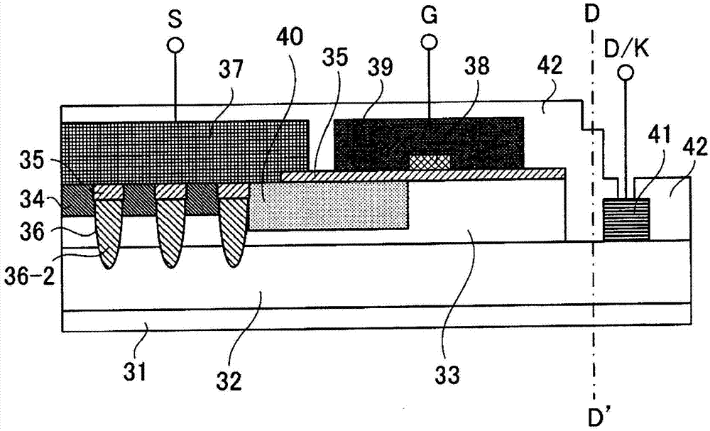
According to one embodiment, in a semiconductor device, a first semiconductor layer of a first conductivity type is formed on a semiconductor substrate of the first conductivity type. A second semiconductor layer of a second conductivity type is formed on the first semiconductor layer at a central portion except an end portion of the semiconductor substrate. A plurality of belt-shaped control electrodes is formed in parallel through a first insulating film on a surface of the second semiconductor layer. A third semiconductor layer of the first conductivity type selectively is formed on a surface of the second semiconductor layer between the control electrodes. A first electrode is formed on the control electrodes through respective second insulating films and is in contact with the third semiconductor layer. A second electrode is formed on the first semiconductor layer at the end portion of the semiconductor substrate.

Description

[0001] Cross-References to Associated Applications [0002] This application is based on and benefits from prior Japanese Patent Application No. 2012-068628 filed on March 26, 2012, and the entire content thereof is hereby incorporated by reference. technical field [0003] All of the embodiments described here relate to semiconductor elements. Background technique [0004] At present, the rated value of the commonly used mobile phone battery is about 3.8V, and the rated value of the power supply voltage of the charging circuit for the battery is 5V. Therefore, if the battery is charged by directly connecting the power supply and the battery, an overvoltage is applied to the battery, which causes a failure of the battery. Therefore, a resistor is inserted between the power supply and the battery via a switching MOSFET, and the voltage is lowered from 5V to 3.8V to provide it. [0005] However, if only resistors are used, there is a problem that current flows backward from ...

Claims


Application Information

Patent Timeline
IPC IPC(8): H01L27/06
CPCH01L27/04H01L27/0629H01L2224/0603
Inventor 小笠原将明新井隆太细井重广
Owner KK TOSHIBA
Learn More