
Control method of edge portion strip shape of cold rolling strip steel

A technology of strip shape control and strip edge, which is applied in the direction of contour control, etc., can solve the problems of not being able to give full play to the rapid response of bending rolls, not being able to reflect small deviation waves in the area near the edge, and long delays in strip shape detection.

Active Publication Date: 2012-09-26
BAOSHAN IRON & STEEL CO LTD
View PDF2 Cites 42 Cited by
  • Summary
  • Abstract
  • Description
  • Claims
  • Application Information

AI Technical Summary

Problems solved by technology

[0005] The above method has the following shortcomings: (1) The shape deviation obtained by directly subtracting the target shape value from the measured shape value of the edge of the strip cannot accurately reflect the shape state of the edge of the strip, especially the Whether there is a small deviation wave in the area near the edge
(2) Since it takes a long time for the strip steel in the upstream frame to run to the shape meter at the exit of the last frame, the delay of the shape detection is correspondingly long, and the response speed of the axial movement of the roll is slow, and the edge shape control period only longer
Only subtracting the target shape value from the instantaneous measured edge shape value at a certain moment in the current control cycle cannot fully reflect the change of the strip edge shape along the length direction in the same control cycle
(3) Although the response speed of work roll bending and intermediate roll bending is much faster than the response speed of roll axial movement, both adopt the same control cycle, which cannot take advantage of the rapid response of bending control

Method used


Image

  • Control method of edge portion strip shape of cold rolling strip steel
  • Control method of edge portion strip shape of cold rolling strip steel
  • Control method of edge portion strip shape of cold rolling strip steel

Examples


Embodiment

[0173] Taking the double-frame six-roller UCM skin pass mill as an example, the implementation process of the strip edge shape control method of the present invention is supplemented as follows.

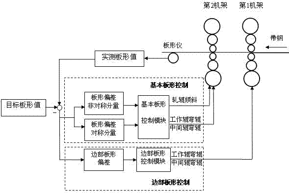
[0174] Such as Figure 5 As shown, the equipment composition relevant to the present invention in the two-frame six-roller UCM skin pass comprises:

[0175] 1) The first frame of the tempering machine has upper and lower work rolls, upper and lower intermediate rolls, upper and lower support rolls, which are used to control the roll tilt of the steel plate shape at the exit of the frame, symmetrical bending rolls of the work rolls, and intermediate rolls. Symmetrical bending rolls, and plate-shaped actuators such as axial long-stroke roll shifting of intermediate rolls, etc.

[0176] 2) The second frame tempering machine has upper and lower work rolls, upper and lower intermediate rolls, upper and lower support rolls, which are used to control the roll tilt of the steel plate shape ...


PUM


Abstract

The invention relates to a rolling method of cold rolling strip steel, in particular to a control method of edge portion strip shape of thin strip steel rolled by a cold continuous rolling mill or a two-stand temper mill. In a strip shape feedback control system centered on a last stand and on the basis of fundamental strip shape control function of major control for conventional edge waves and center waves, the method identifies the state of the edge portion strip shape of the strip steel based on the difference between the actual measured strip shape of strip steel edge portion together with the adjacent areas at the exit of last stand and an objective strip shape, and adjusts the corresponding strip shape executive mechanisms of the last stand and the rest stands according to the state of the edge portion strip shape to realize effective control for the edge portion strip shape of the strip steel, such as small edge waves and small side waves, thereby further improving the quality of the strip steel after cold rolling or temper rolling.

Description

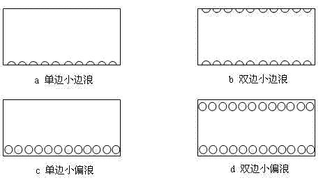
technical field [0001] The invention relates to a rolling method of cold-rolled strip steel, in particular to a method for controlling the edge shape of thin strip steel rolled by a cold tandem rolling mill or a double-stand tempering mill. Background technique [0002] When cold-rolling or flattening thin strip steel (especially ultra-thin strip steel with a thickness of ≤0.3mm), when the local deformation of one or both sides of the strip steel is larger than that of the adjacent area of ​​the edge, the width of the strip edge is relatively large. In a narrow range, local open edge waves with relatively small wave height and wave distance are likely to appear, that is, small edge waves, also known as broken edge waves, etc.; When it is large, local closed edge waves with relatively small wave height and wave distance are likely to appear in the narrow range of width near the edge of the strip, that is, small partial waves. In this paper, small side waves and small sid...

Claims


Application Information

Patent Timeline
IPC IPC(8): B21B37/28
Inventor 顾廷权吴首民王康健潘亮李秀军
Owner BAOSHAN IRON & STEEL CO LTD
Learn More