
Coupling inductance-based power signal composite transmission system

A technology of power signal and transmission system, which is applied in the field of power signal composite transmission system, can solve the problems of lack of universality, achieve the effect of improving intelligence level, portability and reducing volume

Active Publication Date: 2015-02-04
ZHEJIANG UNIV
View PDF5 Cites 0 Cited by
  • Summary
  • Abstract
  • Description
  • Claims
  • Application Information

AI Technical Summary

Problems solved by technology

However, this method is only limited to the synchronous transmission of energy and information at the input end of the Boost circuit with an energy storage inductor on the input side, and it is powerless for the output end of the Boost circuit and other DC-DC topological forms, and is not universal.

Method used


Image

  • Coupling inductance-based power signal composite transmission system
  • Coupling inductance-based power signal composite transmission system
  • Coupling inductance-based power signal composite transmission system

Examples


Embodiment Construction

[0036] In order to describe the present invention more specifically, the technical solutions of the present invention will be described in detail below in conjunction with the accompanying drawings and specific embodiments.

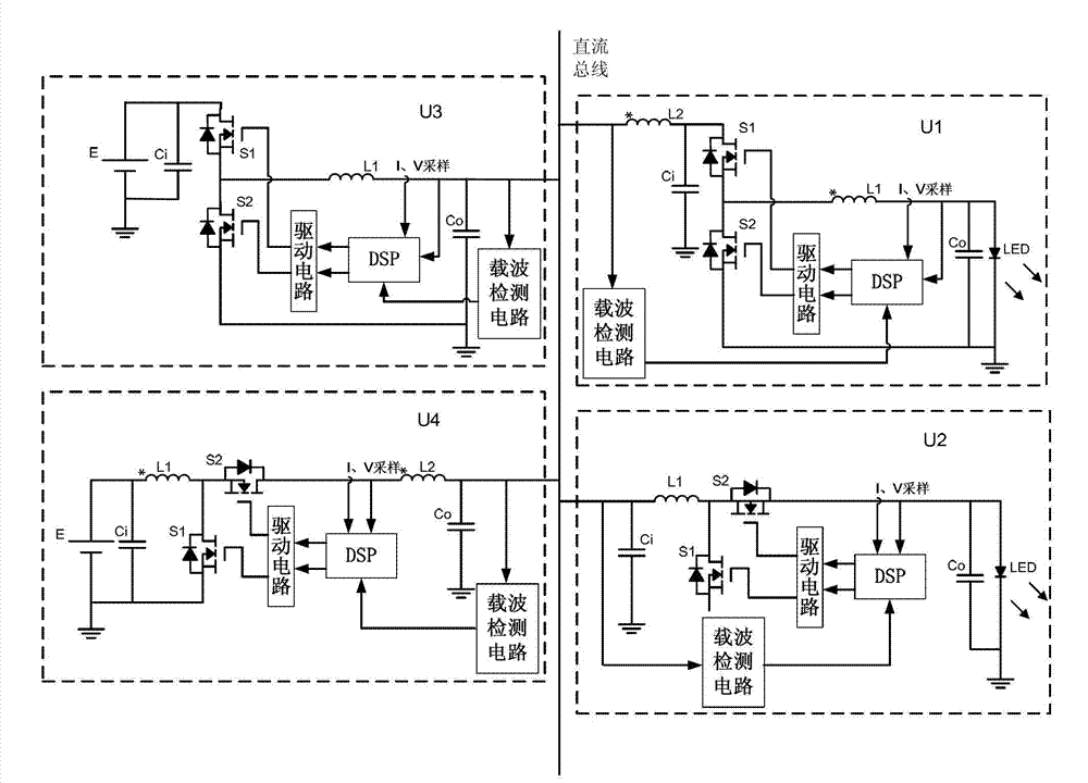
[0037] like figure 1 As shown, a power signal composite transmission system based on coupled inductors, including: a DC bus and four power signal composite transmission units U1~U4, the input or output ends of the four power signal composite transmission units are connected through the transmission inductor and DC bus connection; where:

[0038] The input ends of the power signal composite transmission units U1-U2 are connected to the DC bus through the transmission inductor, and the output terminals are connected to the LED load; the output terminals of the power signal composite transmission units U3-U4 are connected to the DC bus through the transmission inductor, and the input terminals are connected to the DC source.

[0039] The power signal compos...


PUM


Abstract

The invention discloses a coupling inductance-based power signal composite transmission system, which comprises a direct current bus and a plurality of power signal composite transmission units, wherein the input end or the output end of each power signal composite transmission unit is connected with the direct current bus through a transmission inductor. According to the property of a switching power supply, ripple waves which naturally exist in the switching motion process of a DC-DC (direct current-direct current) converter are used as communication carrier waves, coupling inductance is added to the converter to couple inherent stable switching ripple wave signals on an energy storage inductor in the DC-DC converter to the input end or the output end of a circuit, accordingly the signals are transmitted to the public direct current bus, the restriction by the DC-DC topological mode is avoided, on the premise of not adding extra communication lines and modulator circuits, the coupling method is used for transmitting the stable switching signals to the direct current bus, so the composite transmission of the power signals is realized, and the converter can realize sharing of data communication input into or output out of the direct current bus.

Description

technical field [0001] The invention belongs to the technical field of power electronic communication, and in particular relates to a power signal composite transmission system based on coupled inductance. Background technique [0002] With the continuous development of my country's smart grid and new energy power generation systems, the application of power electronic equipment is becoming more and more extensive, such as smart meter reading technology, new energy power generation grid connection technology, etc., are all popular applications in the field of power electronics. In view of this, The intelligence level of power electronic equipment also needs to be improved urgently. For the widely used distributed control system composed of power electronic equipment, in order to better realize its functions and ensure the stable, reliable and coordinated work of the system, it is necessary to realize the comprehensive intelligence of the system, which requires various Power ...

Claims


Application Information

Patent Timeline
Patent Type & Authority Patents(China)
IPC IPC(8): H04B3/54
Inventor 王睿驰杜进王智博吴建德何湘宁
Owner ZHEJIANG UNIV
Learn More