
Telescope array optical signal reception method and telescope array optical signal reception device based on self-adaptation control

An adaptive control and receiving method technology, applied in the field of telescope array optical signal reception, can solve the problems of low sensitivity, low efficiency of receiving signals, and reduce the performance of communication systems, etc., achieve high sensitivity, improve receiving sensitivity and signal-to-noise ratio

Active Publication Date: 2013-10-23
HARBIN INST OF TECH SHENZHEN GRADUATE SCHOOL
View PDF4 Cites 10 Cited by
  • Summary
  • Abstract
  • Description
  • Claims
  • Application Information

AI Technical Summary

Problems solved by technology

Therefore, its harsh channel environment results in weak received signals, large distortion, and strong background noise.
Due to the low signal efficiency, low sensitivity and high bit error rate of the traditional photoelectric detection technology in the case of weak signal and strong background interference, the performance of the entire communication system is reduced, thus limiting the wide application of FSO technology

Method used


Image

  • Telescope array optical signal reception method and telescope array optical signal reception device based on self-adaptation control
  • Telescope array optical signal reception method and telescope array optical signal reception device based on self-adaptation control

Examples


Embodiment Construction

[0021] The present invention will be further described below in conjunction with the accompanying drawings and specific embodiments.

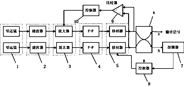
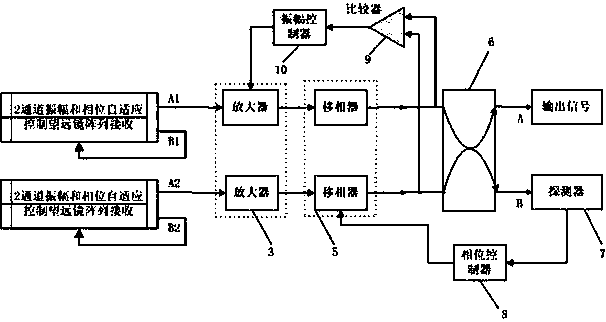
[0022] figure 1 with figure 2 The reference numbers in the drawings are: telescope array 1; filter 2; amplifier 3; Fabry-Perot etalon 4 (abbreviated as F-P); phase shifter 5; 50:50 single-mode polarization-maintaining fiber directional coupler 6 ; detector 7; phase controller 8; comparator 9; amplitude controller 10.

[0023] A telescopic array optical signal receiving method based on amplitude and phase adaptive control described in the technology of the present invention can be used to form a (arbitrary) multi-channel telescope array optical signal receiving system.

[0024] Wherein, the principle of the 2-channel amplitude and phase adaptive control telescope array receiving device can be referred to figure 1 ,Such as figure 1 As shown, the telescope array receiving device composed of two telescope channels includes a telescope array, a...


PUM


Abstract

The invention provides a telescope array optical signal reception method based on self-adaptation control of amplitudes and phases. The method comprises the following steps of A, realizing multi-element array reception on optical signals by a telescope array; B, amplifying and filtering the optical signals coming out of each telescope channel successively; C, controlling phase shifters by the feedback of the output end of a superposition output unit to realize the self-adaptation control on the phases, and controlling amplification factors of amplifiers by the feedback of output ends of the amplifiers to realize the self-adaptation control on the amplitudes; and D, enabling the optical signals of all the channels to enter the superposition output unit for coherent superposition after the self-adaptation control of the phases and the self-adaptation control of the amplitudes are performed on the optical signals to obtain high-sensitivity output signals. The invention also provides a telescope array optical signal reception device based on the self-adaptation control of the amplitudes and the phases. The telescope array optical signal reception method and the telescope array optical signal reception device based on the self-adaptation control of the amplitudes and the phases provided by the invention have the beneficial effect that high-sensitivity and high-signal to noise ratio reception is realized on wireless optical signals under the conditions of strong background interference and weak optical signals.

Description

technical field [0001] The invention relates to a method and device for receiving optical signals of a telescope array based on amplitude and phase adaptive control, in particular to a method and device based on amplitude and phase self-adaptive control that can realize high sensitivity of wireless optical signals under strong background interference and weak optical signals. Adaptive control telescope array receiving method and device. Background technique [0002] The generation of the receiving telescope array is for high-resolution observation from space. The telescope array superimposes the images received by each sub-telescope through an algorithm to obtain higher performance, and its efficiency is greater than that of a single telescope. [0003] Adaptive optics solves the influence of dynamic disturbances such as atmospheric turbulence by measuring the wavefront error of atmospheric turbulence and compensating it in real time. The core of its idea is to introduce a ...

Claims


Application Information

Patent Timeline
IPC IPC(8): H04B10/60
Inventor 姚勇于本双赵宇峰刘超
Owner HARBIN INST OF TECH SHENZHEN GRADUATE SCHOOL
Learn More