Pneumatic pawl manipulator

A technology of manipulators and air claws, applied in the field of plastic processing machinery, can solve the problems of small number of manipulators, increase of machine volume and floor space, etc., and achieve the effect of compact structure, convenient maintenance and replacement, and low energy consumption

Inactive Publication Date: 2013-10-30
台州迈格机械模具有限公司
View PDF0 Cites 4 Cited by
  • Summary
  • Abstract
  • Description
  • Claims
  • Application Information

AI Technical Summary

Problems solved by technology

In the existing manipulator, its two clamping arms are respectively installed on the driving device. During the action, the two clamping arms rotate around their respective rotation axes respectively. When the clamping arms are opened, the distance in the horizontal direction is relatively large. The distance between the manipulators is

Method used


Image

  • Pneumatic pawl manipulator
  • Pneumatic pawl manipulator
  • Pneumatic pawl manipulator

Examples


Embodiment Construction

[0017] The structure of the present invention will be described in further detail below in conjunction with the accompanying drawings and specific embodiments, and the parts in the present invention that are the same as those of the prior art will be referred to the prior art.

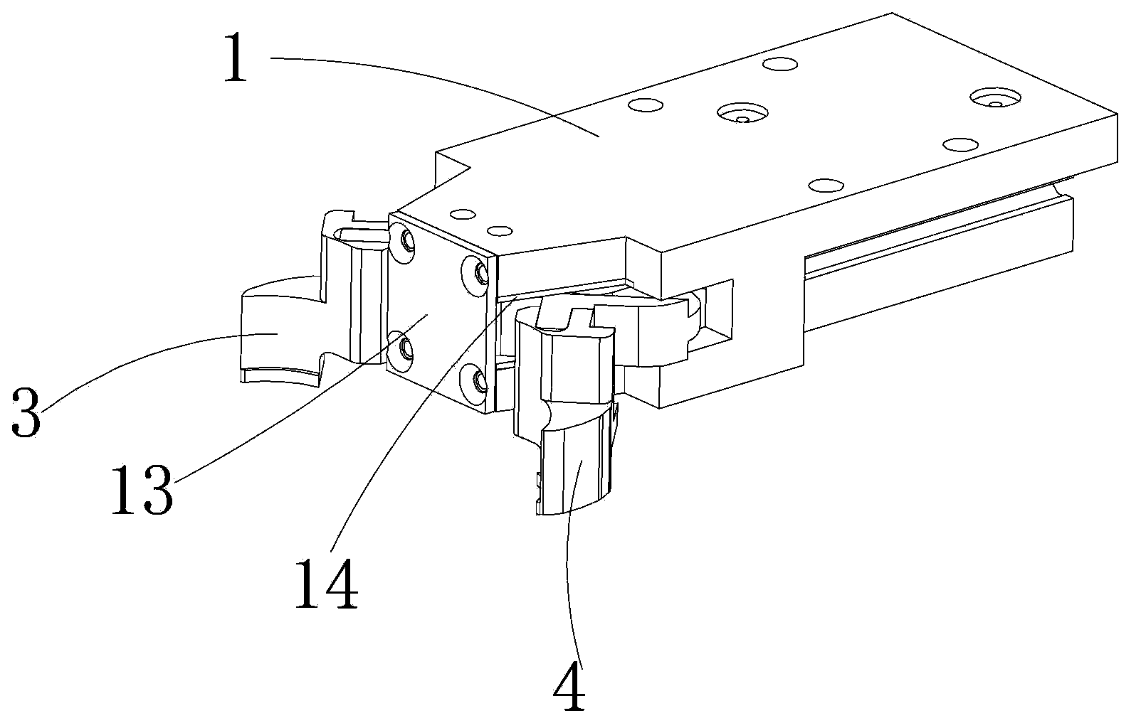
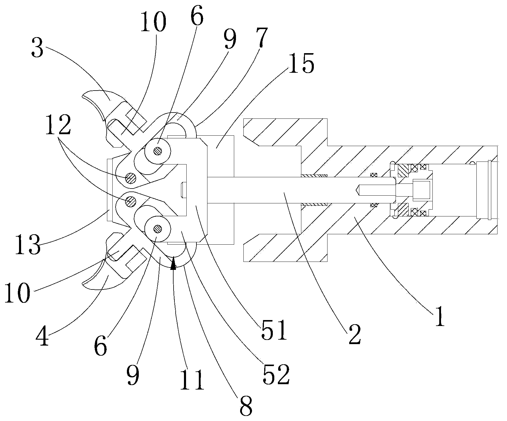
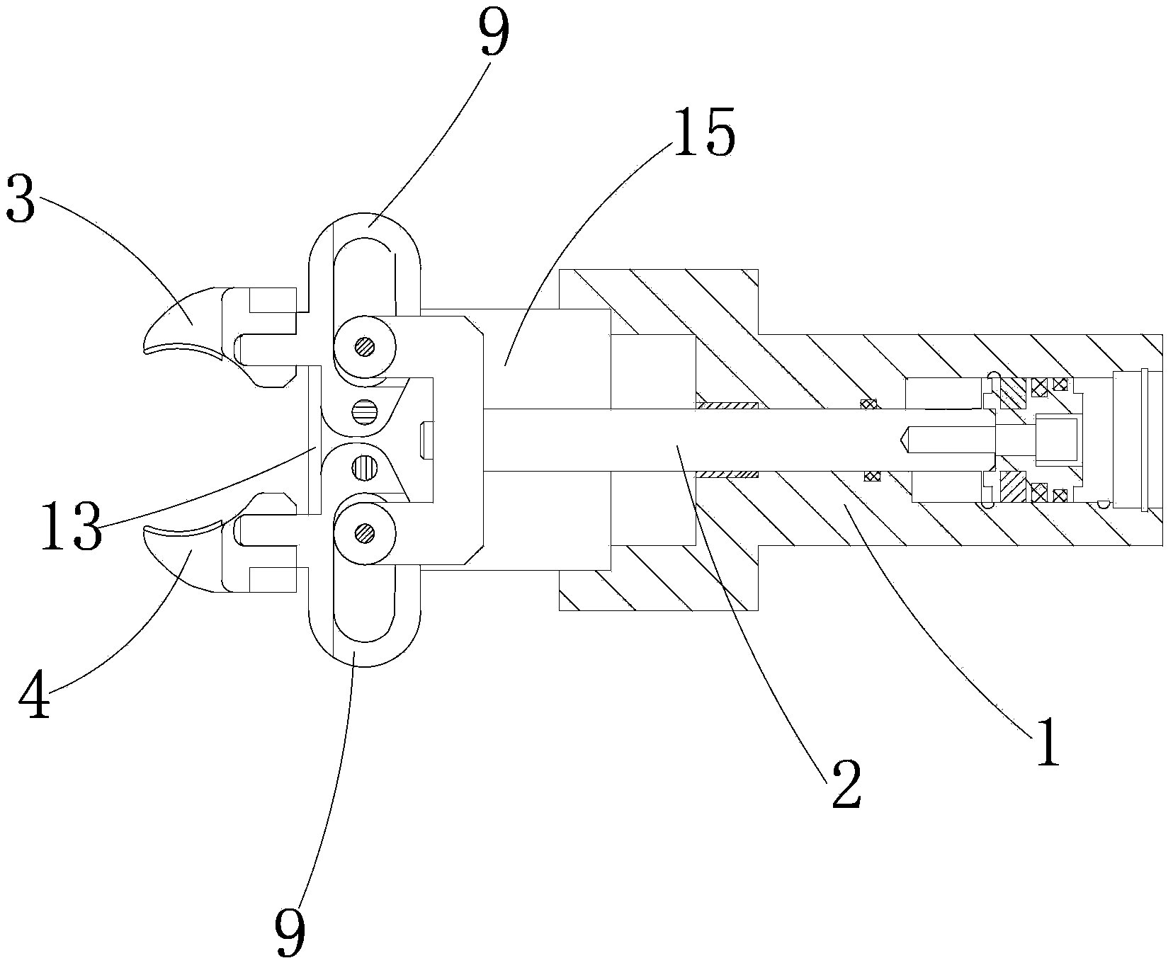
[0018] Such as Figure 1-5 As shown, the air claw manipulator includes a cylinder body 1, a piston, a cylinder rod 2, and a pair of clamping arms connected to the cylinder rod 2 that can be relatively gathered and opened, which are called the left clamping arm 3 and the right clamping arm 4 herein. One end of the cylinder rod 2 is connected with the piston, and the other end is connected with the clamp arm. One end of the cylinder rod 2 connected with the clamp arm is provided with a U-shaped frame 5. The U-shaped frame 5 has a transverse arm 51 in a horizontal direction and two vertical arms. The vertical arm 52 and the cross arm 51 are connected to the cylinder rod 2, and the ends of the two vertical...


PUM


Abstract

The invention discloses a pneumatic pawl manipulator and belongs to the field of plastic processing machinery technology. The manipulator comprises a cylinder body, a piston, a cylinder rod and a pair of clamp arms connected to the cylinder rod and capable of gathering together and opening relatively. The manipulator is characterized in that one end of the cylinder rod connected to the clamp arms is provided with a U-shape rack; a transverse arm of the U-shape rack is connected to the cylinder rod; end portions of two vertical arms of the U-shape rack are respectively provided with a bearing; the pair of clamp arms are respectively slidably connected to the two vertical arms of the U-shape rack through a support with a bearing groove; the bearing runs in the bearing groove; and the support is connected to the cylinder body through a support pin. The invention has the advantages of simple structure, compactness, small volume and low energy consumption, etc.

Description

technical field [0001] The invention relates to a manipulator, in particular to an air claw manipulator, which is used for clamping and conveying plastic pipe blanks, and belongs to the technical field of plastic processing machinery. Background technique [0002] All kinds of plastic bottles such as mineral water bottles, cosmetic bottles, medicine bottles, etc. are widely used in daily life, medicine, chemical industry and other fields. Plastic bottle blowing machine is the most common machine for producing plastic bottles in the market, mainly including frame, heating device, spacing device, conveying device, bottle blowing device and other components. After the steps, enter the mold for blow molding. In the conveying process of each link, it is often necessary to clamp and convey the preform by the preform clamping manipulator. During the working process, the clamping manipulator needs to perform a series of opening and closing actions. In the existing manipulator, it...

Claims


Application Information

Patent Timeline
IPC IPC(8): B29C49/42B25J15/08
Inventor 蔡佳翰
Owner 台州迈格机械模具有限公司
Why Eureka
Try Eureka