Transmission grid fault detection system and method based on internet of thing technology
An Internet of Things technology and fault detection technology, applied in the transmission network fault detection system and field based on Internet of Things technology, can solve the problems of no data transmission and analysis technology, and achieve convenient and efficient troubleshooting, reduce the scope of power outages, and improve versatility Effect
- Summary
- Abstract
- Description
- Claims
- Application Information
AI Technical Summary
Problems solved by technology
Method used
Image
Examples
Embodiment 1
[0041] Embodiment 1, phase-to-phase short-circuit fault handling
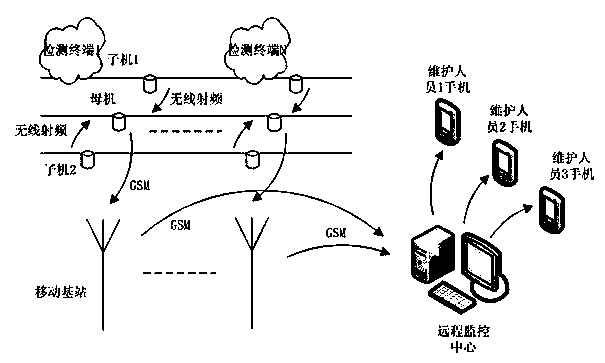
[0042] The fault detection system runs on the overhead transmission line, such as Figure 6 As shown, the first slave machine 1, the second slave machine 3, and the first master machine 2 form the first detection terminal 1; the third slave machine 4, the fourth slave machine 6, and the second master machine 5 form the second detection terminal 2; The fifth slave machine 7, the sixth slave machine 9, and the third master machine 8 form the third detection terminal 3, and the first slave machine 1, the first master machine 2, and the second slave machine 3 respectively detect the three phases of line A, B, and C of line 2 Power transmission line, the third sub-unit 4 and the fifth sub-unit 7 detect the A-phase line of the a branch, the second main unit 5 and the third main unit 8 detect the a-branch B-phase line, the fourth sub-unit 6, and the sixth sub-unit 9 Check the C-phase line of the a branch. When a...
Embodiment 2
[0043] Embodiment 2, single-phase ground fault processing
[0044] The fault monitoring system is connected to the overhead transmission line for operation. When a single-phase ground fault occurs, such as Figure 7 As shown, the first slave machine 1, the second slave machine 3, and the first master machine 2 form the first detection terminal 1; the third slave machine 4, the fourth slave machine 6, and the second master machine 5 form the second detection terminal 2; The fifth slave machine 7, the sixth slave machine 9, and the third master machine 8 form the third detection terminal 3, and the first slave machine 1, the first master machine 2, and the second slave machine 3 respectively detect the three phases of line A, B, and C of line 2 Power transmission line, the third sub-unit 4 and the fifth sub-unit 7 detect the A-phase line of the a branch, the second main unit 5 and the third main unit 8 detect the a-branch B-phase line, the fourth sub-unit 6, and the sixth sub-un...
Embodiment 3
[0045] Embodiment 3, open circuit fault processing
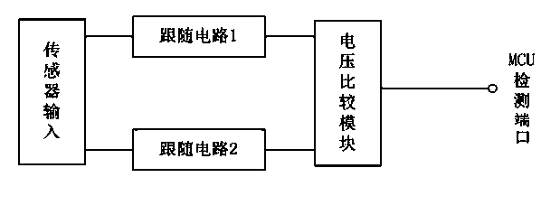
[0046] According to the feature of sudden power failure of the line after the open circuit fault occurs on the overhead transmission line, the present invention designs a line on-off detection circuit to detect the on-off situation of the power system in each line in real time, and judge whether there is an open circuit fault. Open circuit fault judgment circuit such as Figure 4 Shown: The sensor input signal is rectified by diode D1, current limiting resistor R1, filter capacitor C1, and Zener diode D2 are stabilized and enters the LM334 constant current source, and the feedback resistor R2 is set to make the output current provide input for the subsequent photocoupler 6N139 , The output terminal of the photocoupler 6N139 is connected to the power supply through the pull-up resistor R3, and at the same time connected to the MCU detection port. In the case of normal operation of the line, the constant current source always...
PUM
 Abstract
Description
Claims
Application Information
 - R&D
- Intellectual Property
- Life Sciences
- Materials
- Tech Scout
- Unparalleled Data Quality
- Higher Quality Content
- 60% Fewer Hallucinations
Browse by: Latest US Patents, China's latest patents, Technical Efficacy Thesaurus, Application Domain, Technology Topic, Popular Technical Reports.
© 2025 PatSnap. All rights reserved.Legal|Privacy policy|Modern Slavery Act Transparency Statement|Sitemap|About US| Contact US: help@patsnap.com


