General mask and application thereof

A mask plate and lithography machine technology, which is applied to the photolithography process of the pattern surface, the original used for photomechanical processing, and the photolithography process exposure device, etc., can solve the problem of not providing a lithography machine mask, etc. fully compatible

Active Publication Date: 2013-10-30
WUXI CHINA RESOURCES HUAJING MICROELECTRONICS
View PDF3 Cites 6 Cited by
  • Summary
  • Abstract
  • Description
  • Claims
  • Application Information

AI Technical Summary

Problems solved by technology

However, the prior art does not provide a common reticle

Method used


Image

  • General mask and application thereof
  • General mask and application thereof
  • General mask and application thereof

Examples


Embodiment Construction

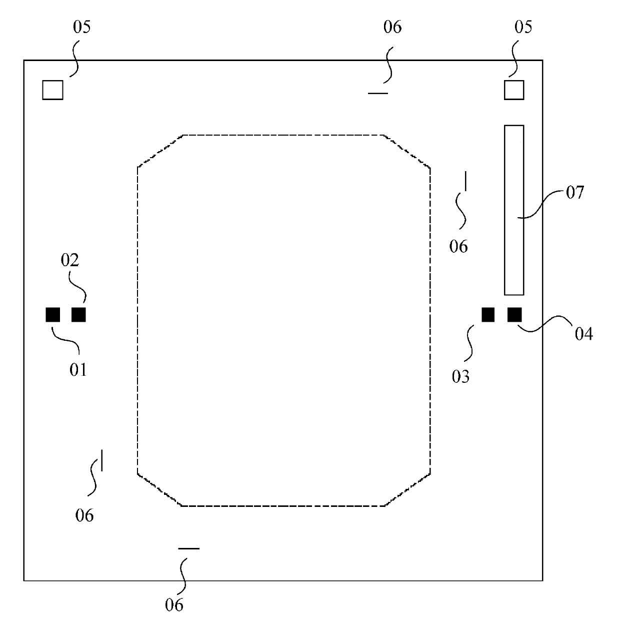
[0021] A pre-designed circuit pattern is printed on the mask plate, through which ultraviolet light shines on the photoresist layer on the wafer to form the circuit pattern of the microprocessor. On a mask plate, in addition to the designed circuit layer graphics, plate alignment marks, silicon wafer coarse alignment marks, silicon wafer fine alignment marks, plate names, numbers and barcodes for automatic identification will be placed at appropriate positions.

[0022] figure 1 Shown is a reticle for ASML on which a part of the above is schematically marked. Among them, reference numerals 01, 02, 03, and 04 represent reticle alignment marks, reference numeral 05 represents reticle pre-alignment marks, and reference numerals 06 denotes a pellicle position line, and reference numeral 07 denotes a barcode. The distance between reticle alignment marks 02 and 03 is 96±0.00015mm, and the distance between reticle alignment marks 01 and 04 is 111±0.00015mm.

[0023] The alignment ...


PUM


Abstract

The invention discloses a general mask for the exposure operation of at least two lithography machines. The general mask comprises a plurality of first mask alignment marks and a plurality of second mask alignment marks, wherein a first mask is used for exposing a first lithography machine; a second mask is used for exposing a second lithography machine. According to the general mask, the alignment sheathing operation between an advanced semiconductor material lithography (ASML) stepped lithography machine and a NIKON stepped lithography machine can be realized.

Description

technical field [0001] The present invention relates to semiconductor technology, and in particular to photolithographic processes and devices used in the manufacture of integrated circuits. Background technique [0002] Photolithography is one of the most important processes in the manufacturing process of integrated circuits. In the silicon wafer manufacturing process, photolithography accounts for about one-third of all costs. Generally, the number of photolithography times and the number of masks required can indicate the difficulty of the integrated circuit production process. A typical silicon integrated circuit process includes more than 15 reticles. [0003] The main equipment used in the lithography process includes lithography machines, and its main manufacturers include ASML (ASML), NIKON (Nikon) and CANON (Canon). Among them, ASML stepper and NIKON stepper are two main semiconductor exposure equipment. There are both ASML steppers and NIKON steppers on the prod...

Claims


Application Information

Patent Timeline
IPC IPC(8): G03F1/42G03F7/20G03F9/00
Inventor 宋矿宝
Owner WUXI CHINA RESOURCES HUAJING MICROELECTRONICS
Why Eureka
Try Eureka