Shuttle kiln for sintering ceramic porous body

A porous body, shuttle kiln technology, applied in the shuttle kiln field, can solve the problem of inability to guarantee the oxygen concentration, and achieve the effects of shortening the firing time, increasing the operating cost, and reducing the temperature difference

Active Publication Date: 2013-11-06
NGK INSULATORS LTD
View PDF6 Cites 8 Cited by
  • Summary
  • Abstract
  • Description
  • Claims
  • Application Information

AI Technical Summary

Problems solved by technology

As a result, the oxygen concentration of the combustion gas generated by the afterburner is only reduced to about 10%, and even if these combustion gases are returned to the furnace, the oxygen concentration in the furnace cannot be guaranteed to be low enough

Method used


Image

  • Shuttle kiln for sintering ceramic porous body
  • Shuttle kiln for sintering ceramic porous body
  • Shuttle kiln for sintering ceramic porous body

Examples


Embodiment Construction

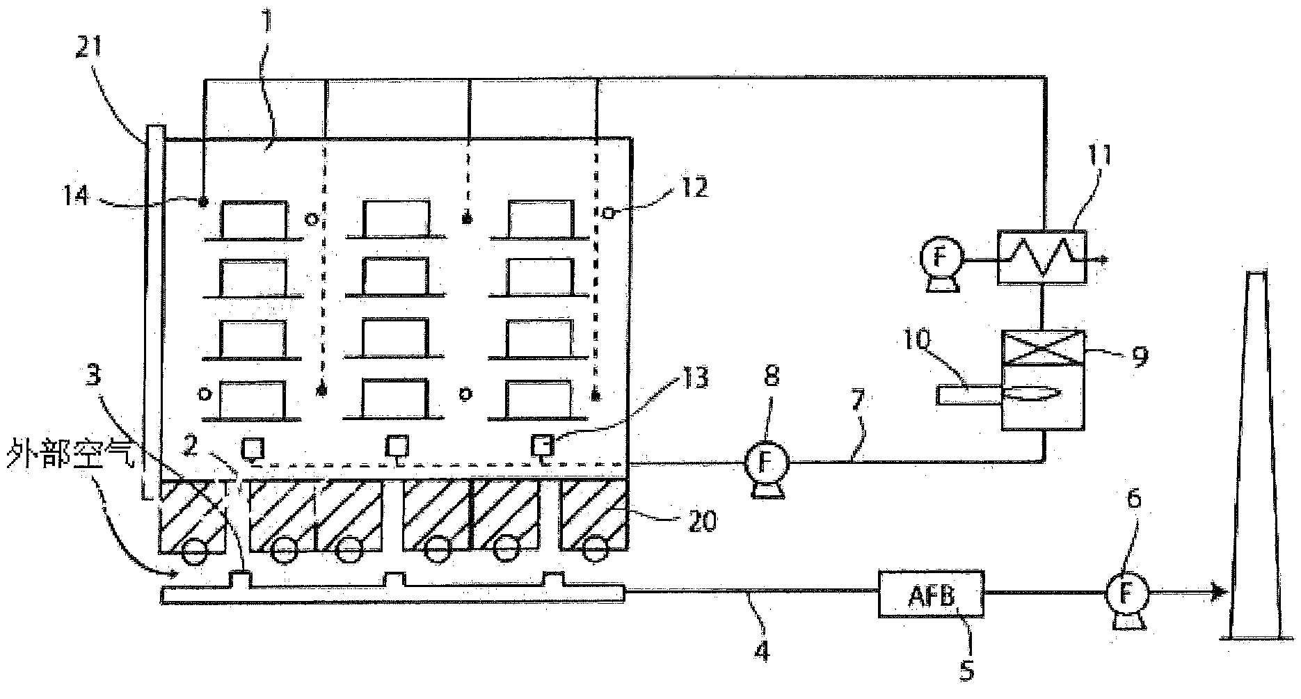
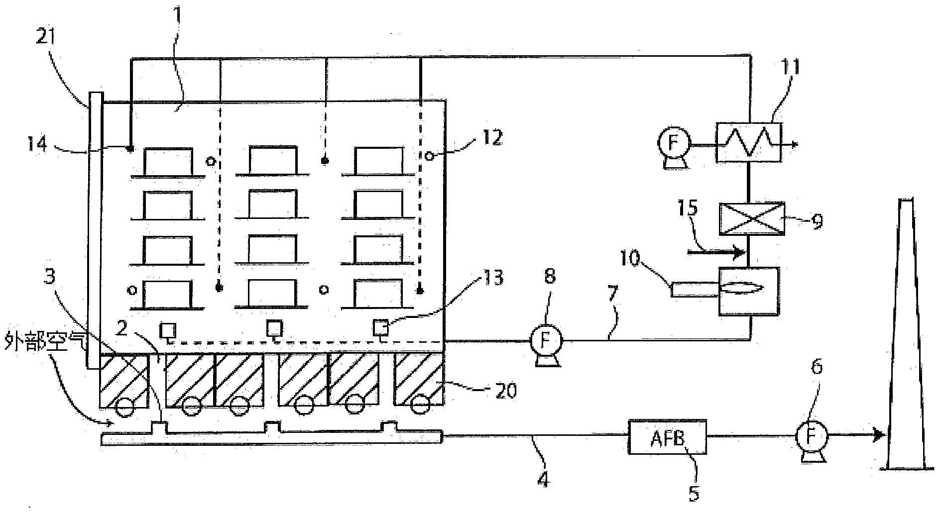
[0031] Preferred embodiments of the present invention will be described below. In this embodiment, the object to be fired is a ceramic honeycomb structure containing an organic binder ceramic porous body. The unfired ceramic porous body is loaded into the furnace by the kiln car, the organic binder is evaporated at about 200°C, and then the temperature is raised to about 1500°C for firing.

[0032] figure 1 Among them, 1 is the furnace body of the shuttle kiln. figure 1 In order to simplify the drawings, it is shown that there are three kiln cars 20 in the furnace. In fact, the furnace body 1 can extend to the left and right of the drawing, open the entrance door 21, and load multiple kiln cars into the furnace 1 for firing. . A gas flow path 2 is formed on the bottom surface of each kiln car 20 . In addition, a gas suction path 4 including a gas suction port 3 is provided at a position corresponding to the gas flow path 2 at the bottom of the kiln car. As mentioned above...


PUM


Abstract

Provided is a shuttle kiln capable of sintering a ceramic porous body containing an organic binder at a shorter time than before and without creating cuts caused by the temperature difference between the inside and the outside. This shuttle kiln is suitable for sintering a ceramic porous body containing an organic binder. The shuttle kiln is provided with a gas suction path (4) for sucking the gas in a furnace and discharging said gas via an afterburner (5), and a circulation path (7) for burning an organic binder gas by sucking the gas in the furnace and discharging said gas to the outside of the furnace and for returning the gas back into the furnace.

Description

technical field [0001] The invention relates to a shuttle kiln for firing ceramic porous bodies containing organic binders, in particular to a shuttle kiln suitable for firing ceramic honeycomb structures. Background technique [0002] As furnaces capable of mass-producing fired ceramic porous bodies, continuous furnaces represented by tunnel kilns and roller kilns, and batch furnaces represented by shuttle kilns have been widely used. The shuttle kiln is a batch-type firing furnace in which the porous body is carried into the furnace by a kiln car. Because the kiln car moves back and forth between the inside and outside of the furnace, it is called a shuttle kiln. [0003] When the ceramic porous body containing the organic binder is fired in a shuttle kiln, a large amount of organic binder vapor is generated from the unfired ceramic porous body at the initial stage of temperature rise. At this time, in order to ensure safety, it is necessary to control the concentra...

Claims


Application Information

Patent Timeline
Patent Type & Authority Applications(China)
IPC IPC(8): F27D17/00C04B35/638F27B17/00
CPCC04B2235/6586C04B2235/6565C04B35/638C04B2235/6562C04B35/64C04B2235/6584C04B38/0006F27D7/06C04B33/32C04B38/06F27B17/0041
Inventor 宫田丈太郎井原尔史安江孝
Owner NGK INSULATORS LTD
Why Eureka
Try Eureka