Eureka AIR delivers breakthrough ideas for toughest innovation challenges, trusted by R&D personnel around the world.

Molten salt battery and method for producing same

A molten salt battery, molten salt technology, applied in the direction of molten electrolyte, secondary battery, airtight storage battery, etc., can solve the problem of discharge shrinkage

Inactive Publication Date: 2013-11-06
SUMITOMO ELECTRIC IND LTD
View PDF2 Cites 6 Cited by
  • Summary
  • Abstract
  • Description
  • Claims
  • Application Information

AI Technical Summary

Problems solved by technology

[0005] However, in practice, a phenomenon occurs that the positive and negative electrodes expand in the stacking direction when charged and contract when discharged
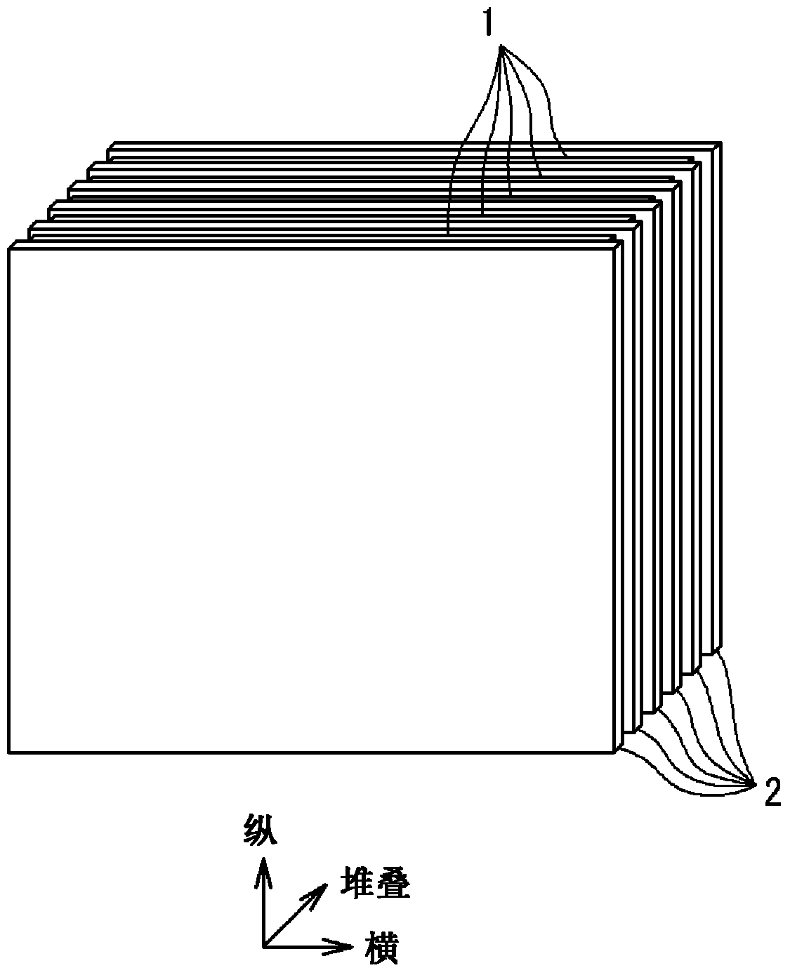
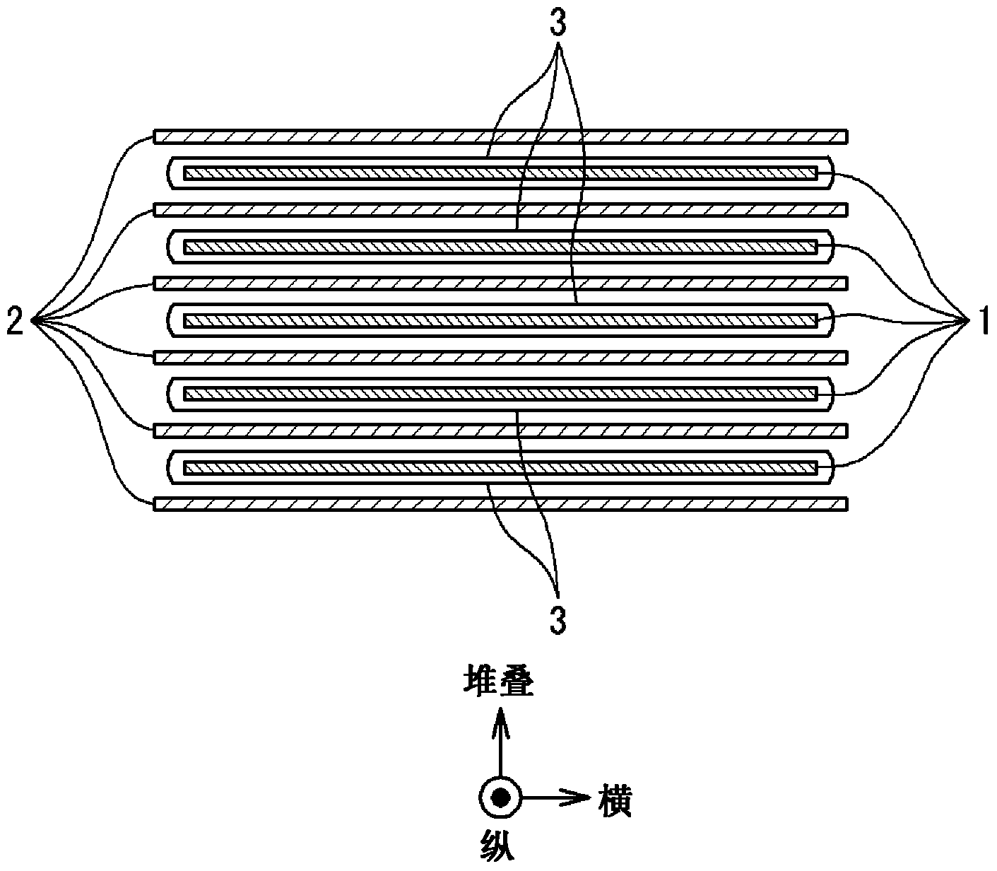
Therefore, a constant crimped state cannot be maintained in the molten salt battery main body only by accommodating the molten salt battery main body in the battery container

Method used


Image

  • Molten salt battery and method for producing same
  • Molten salt battery and method for producing same
  • Molten salt battery and method for producing same

Examples


Embodiment Construction

[0035] A molten salt battery according to one embodiment of the present invention will be described below with reference to the drawings.

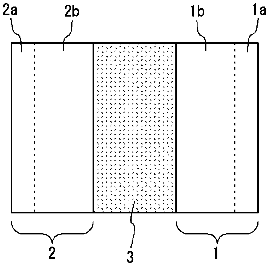
[0036] figure 1 It is a schematic diagram schematically showing the basic structure of a power generating element in a molten salt battery. In the drawing, the power generating element includes a positive electrode 1, a negative electrode 2, and a separator 3 disposed therebetween. The positive electrode 1 includes a positive electrode current collector 1a and a positive electrode material 1b. The negative electrode 2 includes a negative electrode current collector 2a and a negative electrode material 2b.

[0037] The material of the positive electrode current collector 1 a is, for example, aluminum nonwoven fabric (wire diameter: 100 μm, porosity: 80%). By using a mass ratio of 85:10:5:50 to positive electrode active materials such as NaCrO 2, acetylene black, PVDF (polyvinylidene fluoride) and N-methyl-2-pyrrolidone were mixed to ob...


PUM

PropertyMeasurementUnit
thicknessaaaaaaaaaa
melting pointaaaaaaaaaa
thermal resistanceaaaaaaaaaa

Abstract

In order to provide a molten salt battery that can be charged and discharged stably without requiring, as an essential element, an internal elastic component for achieving contact by pressurization, this molten salt battery is provided with: a molten salt battery body in which positive electrodes and negative electrodes are stacked alternately with separators sandwiched therebetween, the separators containing a molten salt as an electrolyte; and a battery case that is made of a flexible material and that seals and covers the molten salt battery body while exposing only the terminals from the positive electrodes and the negative electrodes. The inside of the battery case is brought into a negative pressure state, and thus, the battery case presses the molten salt battery body in the stacking direction due to the external pressure caused by atmospheric pressure.

Description

technical field [0001] The present invention relates to the structure of a battery having a molten salt as an electrolyte and its manufacturing method. The molten salt also includes an ionic liquid that melts at room temperature. Background technique [0002] In recent years, power generation using natural energy such as sunlight and wind power has been promoted as a means of generating electricity without emitting carbon dioxide. When generating power by natural energy, equalization of power supply with respect to load is absolutely necessary because not only the amount of power generation often depends on natural conditions such as climate and weather, but also it is difficult to adjust the amount of power generation according to power demand. In order to achieve equalization by charging and discharging generated electric energy, a storage battery with high energy density / high efficiency and large capacity is required, and as a storage battery satisfying such requirements...

Claims


Application Information

Patent Timeline
Patent Type & Authority Applications(China)
IPC IPC(8): H01M10/39H01M2/02H01M2/06H01M50/105H01M50/119H01M50/121H01M50/124H01M50/136
CPCH01M10/39H01M10/0481H01M2/0202H01M2/0275H01M2300/0048H01M10/0468H01M10/3909H01M2/02H01M2/0237H01M2/0217H01M2300/0054Y02E60/12H01M2/0267H01M10/34Y10T29/49108Y02E60/10H01M50/103Y02P70/50H01M50/105H01M50/121H01M50/124H01M50/136H01M50/119H01M10/399H01M50/138
Inventor 酒井将一郎福永笃史新田耕司稻泽信二
Owner SUMITOMO ELECTRIC IND LTD
Why Eureka
Eureka Blog
Learn More