Non-reciprocal circuit element

A technology of circuit components and ferrite, which is applied in the direction of electrical components, circuits, waveguide devices, etc., can solve the problems of high manufacturing costs, difficult processing of openings, cracking, etc., achieve good mass production, ensure processing allowance, Effect of Good Temperature Characteristics

Inactive Publication Date: 2015-06-17
ORIENT MICROWAVE CORP
View PDF4 Cites 0 Cited by
  • Summary
  • Abstract
  • Description
  • Claims
  • Application Information

AI Technical Summary

Problems solved by technology

[0007] However, in the above-mentioned conventional nonreciprocal circuit element, since many holes for inserting the input and output terminals or holes for penetrating the side walls are perforated on the thin-plate-shaped relatively brittle lower ferrite plate, etc. The opening of the opening, the side wall is used to connect the upper and lower conductor plates to form a closed magnetic circuit, so there are the following problems: the processing of the opening is difficult, the manufacturing cost is high, and if the above-mentioned circuit board is mounted on the surface after surface mounting If bending stress or warping occurs, it is easy to cause cracks starting from the edge of the opening.

Method used


Image

  • Non-reciprocal circuit element
  • Non-reciprocal circuit element
  • Non-reciprocal circuit element

Examples


no. 1 Embodiment approach )

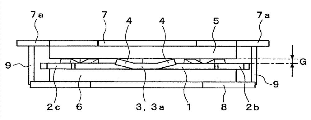
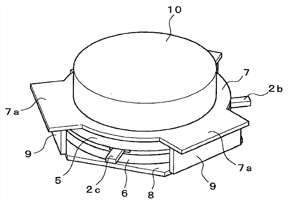
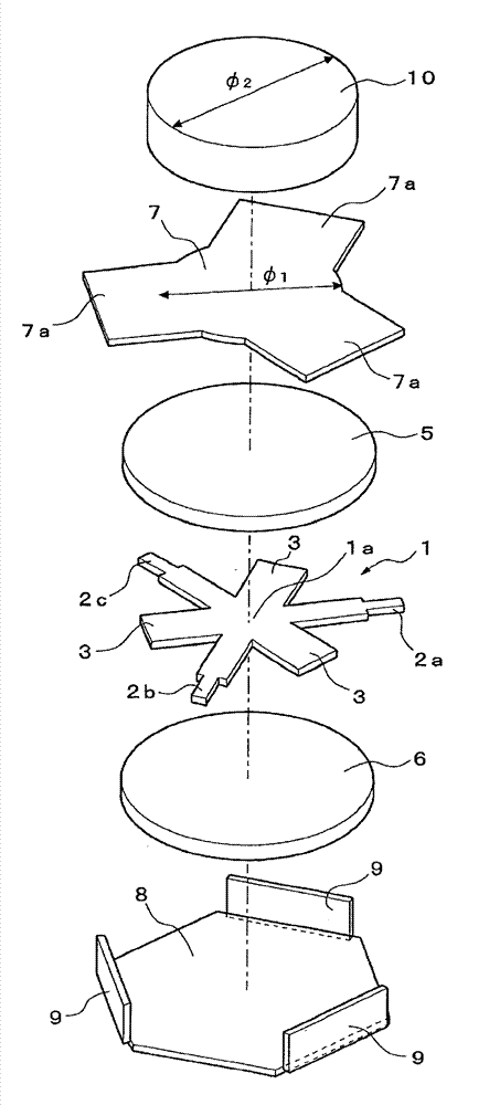
[0056] Figure 1 ~ Figure 4 It is a diagram showing an embodiment in which the non-reciprocal circuit element according to the present invention is applied to an isolator, and the reference numeral 1 in the figure is a center conductor.

[0057] The center conductor 1 is formed of a metal plate such as phosphor bronze, and has input and output terminals 2a, 2b, and 2c that extend radially in three directions from the center portion 1a toward the outside. Here, the input and output terminals 2a, 2b, and 2c have a center angle of 120° between each other, and are formed in a Y-shape as a whole. Between the input and output terminals 2a, 2b, and 2c adjacent in the circumferential direction, they are respectively formed facing outwards. Resonator 3 that extends radially. In addition, the resonator 3 is set to have a shorter length dimension than the input / output terminals 2a, 2b, and 2c.

[0058] In addition, each resonator 3 is formed in a T-shape by forming a protruding portion at it...

no. 2 Embodiment approach )

[0080] Figure 7 ~ Figure 9 This is a diagram showing the second embodiment in which the non-reciprocal circuit element according to the present invention is applied to an isolator. Similar to the above-mentioned first embodiment, the reference numeral 1 in the figure is a center conductor.

[0081] The center conductor 1 is formed of a metal plate such as phosphor bronze, and has input and output terminals 2a, 2b, and 2c that extend radially in three directions from the center portion 1a toward the outside. Here, the input and output terminals 2a, 2b, and 2c have a center angle of 120° between each other and are formed in a Y-shape as a whole. Between the input and output terminals 2a, 2b, and 2c adjacent in the circumferential direction, they are formed with the same outward facing Square resonator 3 extending radially. In addition, the resonator 3 is set to have a shorter length dimension than the input / output terminals 2a, 2b, and 2c.

[0082] In addition, the center conductor...


PUM


Abstract

There is provided a non-reciprocal circuit element which has a simple structure and superiority in assembly and allows easy achievement of height reduction and size reduction while preventing fracture of a ferrite plate. In the present invention, a central conductor 1 in which respective resonators 3 extending outward are formed between I / O terminals 2a to 2c extending outward in a Y-shape from a central portion, upper and lower ferrite plates 5 and 6 between which the central conductor 1 together with the resonators 3 is sandwiched, and upper and lower magnetic metal plates 7 and 8 between which the upper and lower ferrite plates are sandwiched are stacked, a magnet 10 is arranged on the upper magnetic metal plate 7, and bent portions 4 which are bent in out-of-plane directions and form an interstice G between the central conductor 1 and the upper ferrite plate 5 are formed at respective distal end portions 3a of the resonators 3 of the central conductor 1 such that the upper ferrite plate 5 is provided to be capable of coming into and out of contact with the central conductor 1 due to the elasticity of the bent portions 4 The prevent invention also provides a non-reciprocal circuit element which can obtain good circulator characteristics without excessively increasing the magnetic field strength of a magnet and can be used in a wide band including a high frequency band in particular. To this end, in a non-reciprocal circuit element in which the I / O terminals 2a to 2c are integrally formed, and the upper and lower magnetic metal plates 7 and 8 form a closed magnetic circuit via side plates 9, the upper magnetic metal plate 7 is formed of a material having magnetic permeability lower than that of pure iron and / or is formed to have a thickness t smaller than a thickness T of the lower magnetic metal plate 8

Description

Technical field [0001] The present invention relates to a non-reciprocal circuit element such as an isolator or a circulator that is incorporated in various microwave devices and changes the transmission path of microwaves through the rotation of the gyromagnetic phenomenon. Background technique [0002] Generally, non-reciprocal circuit elements such as an isolator or a circulator are mounted on the circuit substrate of a microwave device such as a microwave amplifier or a microwave oscillator. These non-reciprocal circuit elements have a structure in which a magnetic field in one direction is applied to the inside of a magnetic body such as ferrite used for microwave magnetic resonance through a permanent magnet, and a center with input and output terminals is arranged on the surface of the magnetic body The conductor rotates and changes the transmission path of the microwave input from the input / output terminal to other input / output terminals through the right-handed law of gy...

Claims


Application Information

Patent Timeline
Patent Type & Authority Patents(China)
IPC IPC(8): H01P1/36H01P1/387
CPCH01P1/387H01P1/38
Inventor 近田淳二间渕大介
Owner ORIENT MICROWAVE CORP
Why Eureka
Try Eureka