Low power consumption voltage regulator circuit

A technology of voltage regulation circuit and low power consumption, which is applied in the direction of regulating electrical variables, control/regulation systems, instruments, etc., can solve the problems of low efficiency of charge pump, high actual detection voltage, excessive output voltage jitter, etc., to improve efficiency , Reduce power consumption, reduce the effect of high voltage output swing

Active Publication Date: 2013-11-13
SHANGHAI HUAHONG GRACE SEMICON MFG CORP
View PDF6 Cites 23 Cited by
  • Summary
  • Abstract
  • Description
  • Claims
  • Application Information

AI Technical Summary

Problems solved by technology

[0003] However, the voltage regulating circuit of the prior art has the following disadvantages: 1. When only two capacitors (C1 / C2) are used to sample the high voltage HV at the output of the charge pump 10, Vdet=Vc2=HV-Vc1=HV / 2(C1 =C1), the equivalent leakage Ileak2 of C1 makes Vc2>Vc1, that is, the actual detection voltage is higher than the design preset value due to the existence of leakage, so that HV is lower than the design preset value. This situation will be controlled by the control switch S1 When the signal CK is low (the charge pump does not work at this time, the switch S1 of the resistor network is disconnected);
[0004] 2. In order to ensure that the HV is above the required voltage value for a long time, such as greater than 2.5V, the current technology generally chooses to set the highest voltage of the HV to 5V, which limits the voltage regulation circuit and is not suitable for low withstand voltage applications. If the HV is too high, the efficiency of the charge pump will be low, and the output voltage will fluctuate too much.

Method used


Image

  • Low power consumption voltage regulator circuit
  • Low power consumption voltage regulator circuit
  • Low power consumption voltage regulator circuit

Examples


Embodiment Construction

[0017] The implementation of the present invention is described below through specific examples and in conjunction with the accompanying drawings, and those skilled in the art can easily understand other advantages and effects of the present invention from the content disclosed in this specification. The present invention can also be implemented or applied through other different specific examples, and various modifications and changes can be made to the details in this specification based on different viewpoints and applications without departing from the spirit of the present invention.

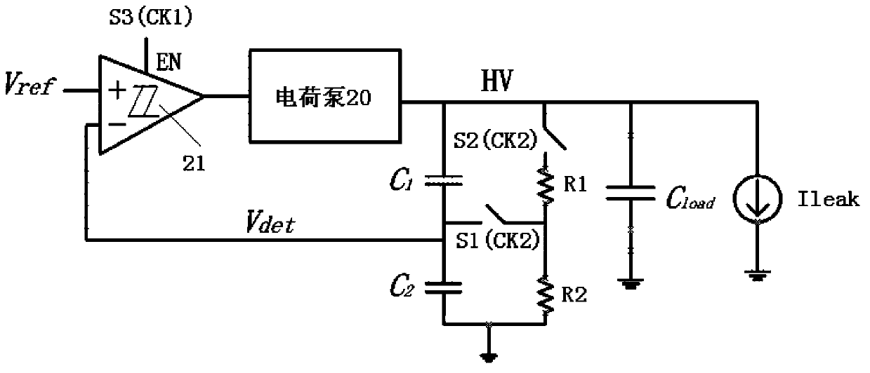
[0018] figure 2 It is a schematic circuit diagram of a low power consumption voltage regulation circuit of the present invention. according to figure 2 , a low power consumption voltage regulation circuit of the present invention, comprising: a charge pump 20, a comparator 21, capacitors C1 / C2 and resistors R1 / R2.

[0019] The charge pump 20 is used to generate the required high voltage...


PUM


Abstract

The invention discloses a low power consumption voltage regulator circuit, which comprises a charge pump, a comparator, a first capacitor, a second capacitor, a first resistor and a second resistor, wherein the comparator is connected with a third switch; the third switch is controlled by a first control signal generated by a subthreshold current oscillator to control the work cycle of the comparator; a resistor-capacitor network is connected with first and second switches; and the first and second switches are controlled by a second control signal generated by the subthreshold current oscillator to control the refresh cycle of a resistor voltage divider to a capacitor voltage divider. By the low power consumption voltage regulator circuit, a detection voltage error in the capacitor voltage divider caused by electric leakage can be avoided, so that the charge pump can normally work to meet the requirement on voltage; and moreover, the highest output voltage of the charge pump is limited to be 2.7V, so that a defect that high voltage resistant devices are required in the prior art is overcome, the high voltage output range is reduced, the efficiency of the charge pump is improved and the power consumption is reduced.

Description

technical field [0001] The invention relates to a voltage regulating circuit, in particular to a low power consumption voltage regulating circuit. Background technique [0002] figure 1 It is a schematic circuit diagram of a voltage regulating circuit in the prior art, such as figure 1 As shown, the voltage regulation circuit includes: a charge pump 10, a comparator 11, capacitors C1 / C2, and resistors R1 / R2. The charge pump 10 generates a high voltage HV, and the capacitors C1 / C2 are connected in series to the output terminal of the charge pump 10 to control the high voltage HV. For sampling, resistors R1 / R2 are connected in series to the output end of the charge pump 10 through a switch, and the middle node of C1 / C2 and the middle node of R1 / R2 are connected to a switch S1, which is used for the resistor divider circuit when the charge pump is working. To quickly charge the capacitor voltage divider circuit, the intermediate node of C1 / C2 is connected to the negative inpu...

Claims


Application Information

Patent Timeline
Patent Type & Authority Applications(China)
IPC IPC(8): G05F1/565
Inventor 张勇杨光军
Owner SHANGHAI HUAHONG GRACE SEMICON MFG CORP
Why Eureka
Try Eureka