Vehicle-mounted composite solar energy and tail gas waste heat recovery absorption refrigeration system

A technology of absorption refrigeration and waste heat recovery, applied in refrigerators, adsorption machines, refrigeration and liquefaction, etc., can solve the problems of inability to remove heat in the car, affecting practical efficiency, overheating of water tanks, etc., to avoid thermal pollution and save fuel. , the effect of saving energy

Inactive Publication Date: 2013-11-20
TIANJIN UNIV
View PDF5 Cites 9 Cited by
  • Summary
  • Abstract
  • Description
  • Claims
  • Application Information

AI Technical Summary

Problems solved by technology

And, when it is parked, the air conditioning system of the car cannot run, and the heat in the car cannot be removed. When people enter the car, it is unbearable. When the car starts to cool quickly, the human body changes from hot to cold quickly. , this process is relatively short, and it is easy to cause certain diseases in the human body
[0004] In automobile air conditioning, the vapor compression air conditioning system is mainly used, which generally consumes 8% to 12% of the power of the automobile engine, of which the compressor accounts for 80% to 85%, and the fan accounts for 15% to 20%. Such a large power consumption is not only Increased fuel consumption, and may cause overheating of the water tank, affecting the power of the car

Method used


Image

  • Vehicle-mounted composite solar energy and tail gas waste heat recovery absorption refrigeration system
  • Vehicle-mounted composite solar energy and tail gas waste heat recovery absorption refrigeration system
  • Vehicle-mounted composite solar energy and tail gas waste heat recovery absorption refrigeration system

Examples


Embodiment Construction

[0031] A vehicle-mounted composite solar energy and exhaust waste heat recovery absorption refrigeration system of the present invention will be described in detail below in conjunction with the embodiments and drawings.

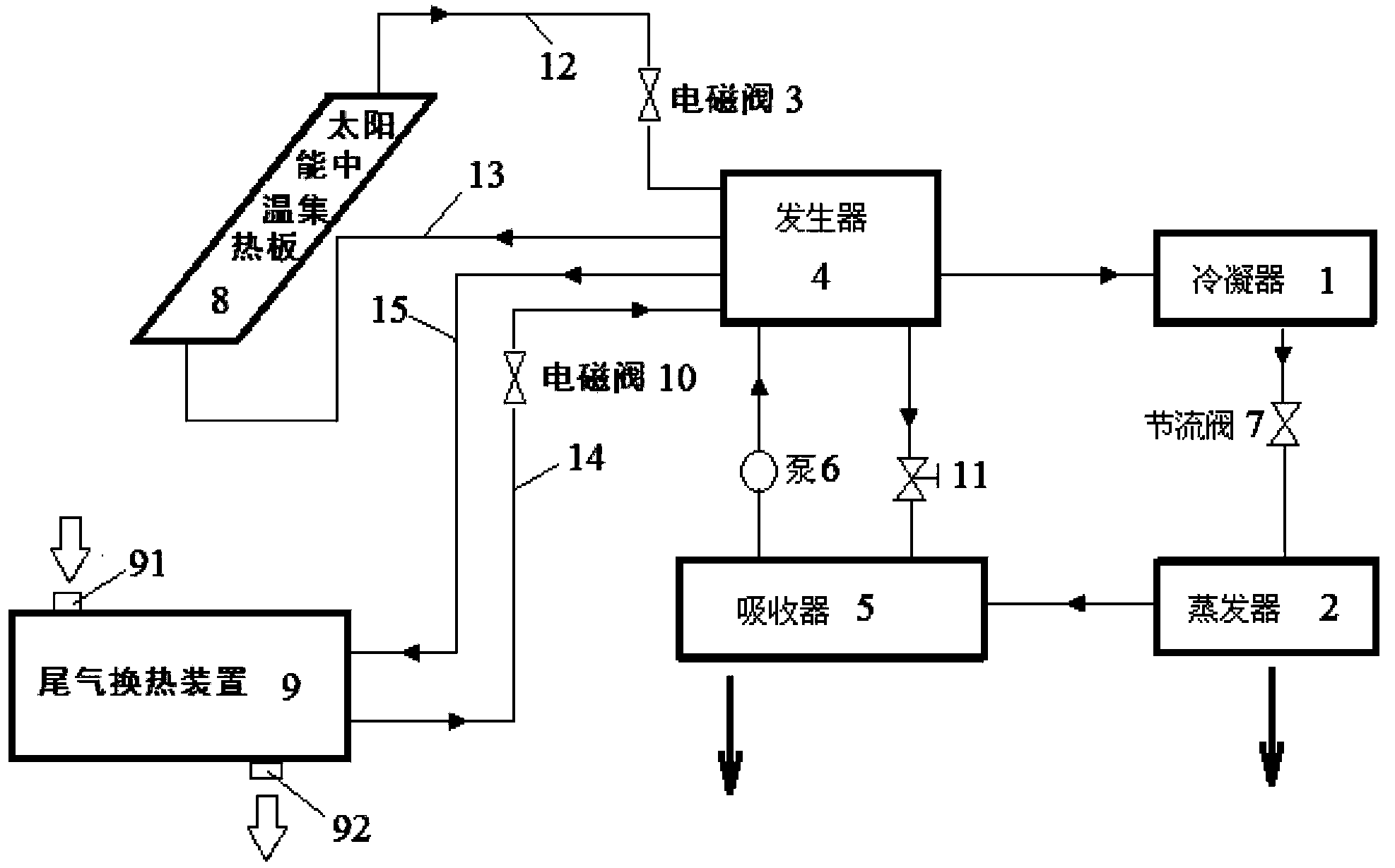
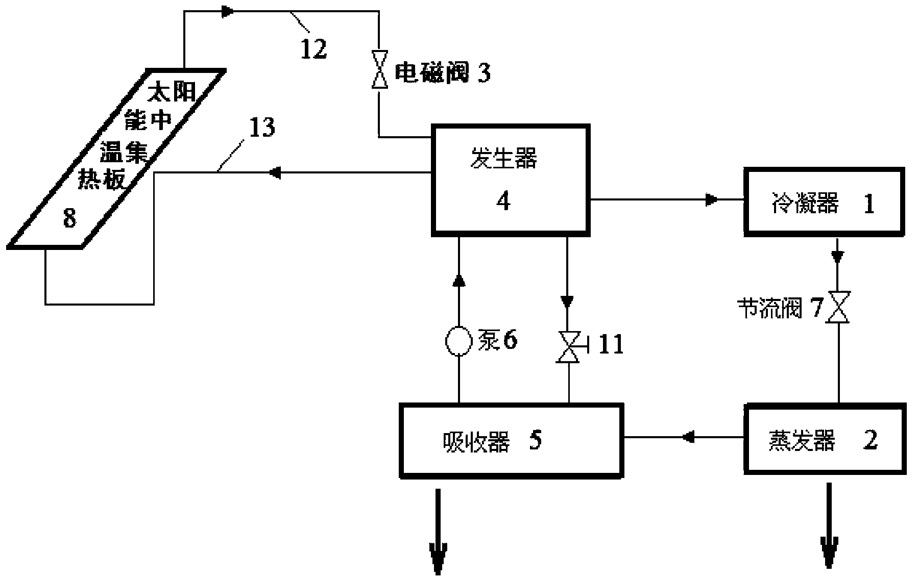
[0032] Such as figure 1 As shown, a vehicle-mounted composite solar energy and tail gas waste heat recovery absorption refrigeration system of the present invention includes a condenser 1, an evaporator 2, an absorber 5 and a generator 4, wherein the liquid refrigerant outlet of the condenser 1 passes through the pipe The gaseous refrigerant outlet of the evaporator 2 is connected to the gaseous refrigerant inlet of the absorber 5 through the pipeline, and the gaseous refrigerant inlet of the absorber 5 is connected with the throttle valve 7 arranged on the pipeline. The mixed liquid outlet is connected to the mixed liquid inlet of the generator 4 through the pipeline and the solution pump 6 arranged on the pipeline, and the absorbent inlet of the absorber 5...


PUM


Abstract

The invention relates to a vehicle-mounted composite solar energy and tail gas waste heat recovery absorption refrigeration system which comprises a condenser, an evaporator, an absorber and a generator. A liquid state refrigerating fluid outlet of the condenser is connected with a liquid state refrigerating fluid inlet of the evaporator, a gas state refrigerating fluid outlet of the evaporator is connected with a gas state refrigerating fluid inlet of the absorber, a mixed liquid outlet of the absorber is connected with a mixed liquid inlet of the generator, an absorbent inlet of the absorber is connected with an absorbent outlet of the generator, a gas state refrigerating fluid outlet of the generator is connected with a gas state refrigerating fluid inlet of the condenser, a heat exchange pipe which is used for conducting heat exchange with mixed liquid in the generator is arranged in the generator, and the heat exchange pipe in the generator is connected with a heat generation device through a water inlet-outlet pipe arranged outside the generator. According to the vehicle-mounted composite solar energy and tail gas waste heat recovery absorption refrigeration system, before a vehicle is started, energy sources are provided by the solar energy, and after the vehicle is started, the energy sources are provided by the tail gas waste heat of the vehicle. Therefore, the energy resources are saved, the heat pollution of the tail gas of the vehicle to the atmosphere is avoided, and the requirement of human bodies for comfort of the heat environment is met.

Description

technical field [0001] The invention relates to a vehicle refrigeration system. In particular, it relates to a vehicle-mounted composite solar energy and tail gas waste heat recovery absorption refrigeration system. Background technique [0002] Existing automotive air-conditioning technology is usually: the automotive air-conditioning refrigeration system is composed of a compressor, a condenser, a liquid storage drier, an expansion valve, an evaporator, and a blower. Copper tubes (or aluminum tubes) and high-pressure rubber tubes are used to connect each component to form a closed system. When the refrigeration system is working, the refrigerant circulates in this closed system in different states. Each cycle has four basic processes: 1. Compression process: the compressor sucks the low-temperature and low-pressure refrigerant gas at the outlet of the evaporator, and puts it The gas compressed into high temperature and high pressure is discharged from the compressor. 2....

Claims


Application Information

Patent Timeline
Patent Type & Authority Applications(China)
IPC IPC(8): B60H1/32F25B15/00F25B27/00F25B27/02
CPCY02A30/274
Inventor 龚原穆贻德李晋文韩勇提博雯
Owner TIANJIN UNIV
Why Eureka
Try Eureka