
Circulating water cooling system and technical flow thereof

A technology for cooling circulating water and process flow, applied in cooling fluid circulation devices, household refrigeration devices, lighting and heating equipment, etc., can solve the problems of long steam heating time, high circulating water temperature, low production efficiency, etc. Fuel and make-up water, low inlet water temperature, improved production efficiency

Inactive Publication Date: 2013-11-20
DIHON PHARMA GROUP
View PDF4 Cites 3 Cited by
  • Summary
  • Abstract
  • Description
  • Claims
  • Application Information

AI Technical Summary

Problems solved by technology

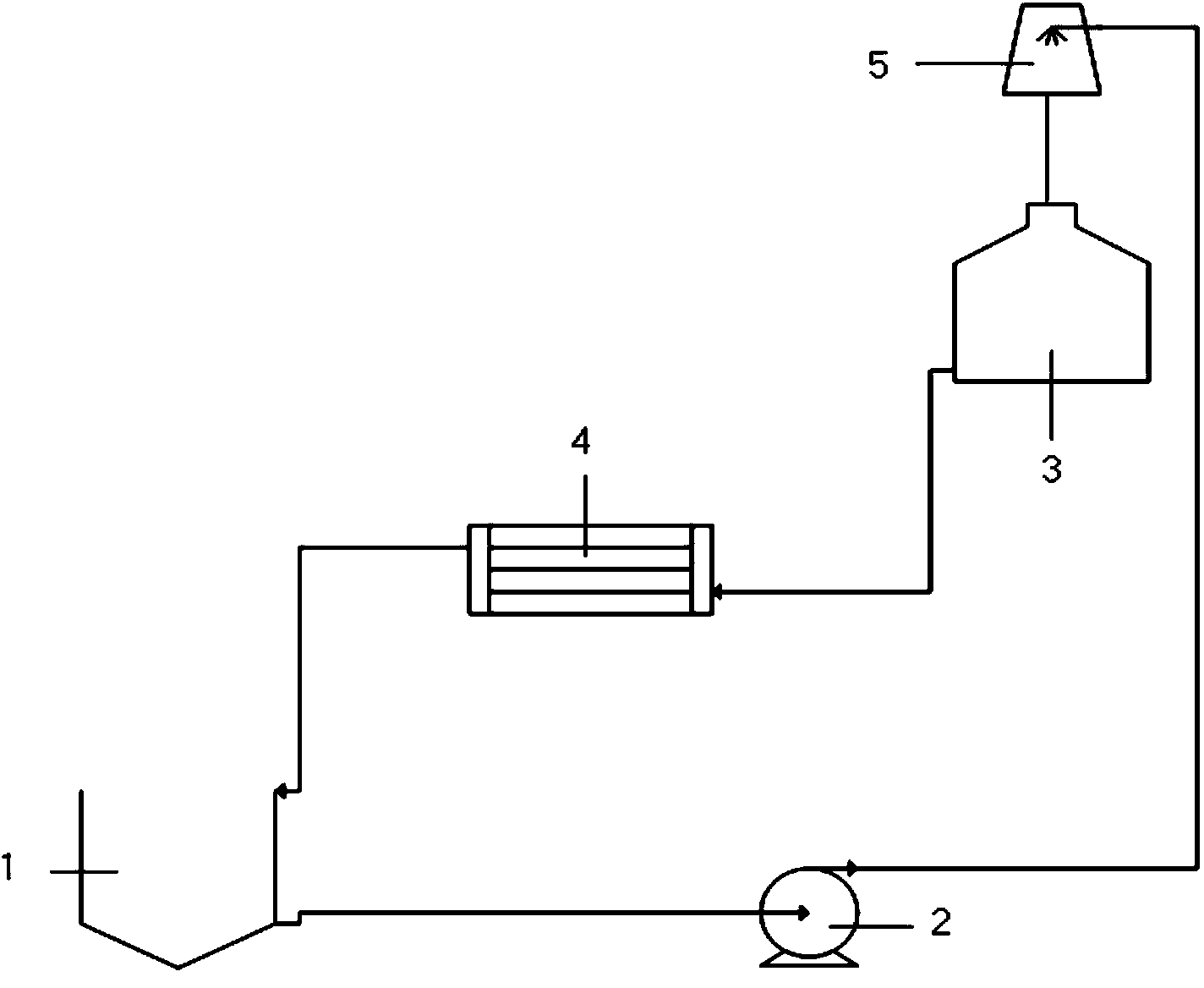
[0004] After actual production and application, it is found that the above-mentioned cooling circulating water system is used to cool the production equipment. Since the production equipment will generate a lot of heat, the temperature of the circulating water coming out of the condenser of the production equipment is relatively high, and the water with a high temperature flows directly into the circulation. The water pool will cause the overall temperature of the circulating water in the entire circulation system to be high, the cooling effect is poor, and the production efficiency is low. It can only meet the utilization rate of 50% of the production equipment in the workshop. The steam heating time is long, and the natural evaporation of 20 Tons of water, drinking water needs to be replenished in time, the equipment has low production capacity and high consumption, so further improvement is urgently needed

Method used


Image

  • Circulating water cooling system and technical flow thereof
  • Circulating water cooling system and technical flow thereof
  • Circulating water cooling system and technical flow thereof

Examples


Embodiment Construction

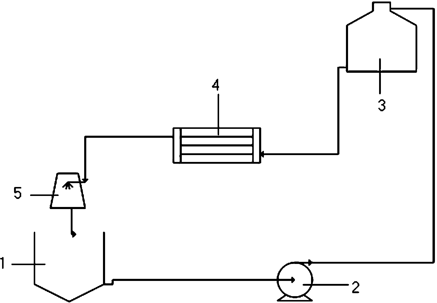
[0022] A cooling circulating water system of the present invention is applied to water cooling production equipment, such as image 3 As shown, it includes the circulating water pool 1, the condenser 4 of the production equipment, and the cooling device for circulating water (the cooling tower 5 is used in this embodiment), wherein the circulating water pool 1, the condenser 4 of the production equipment and the cooling tower 5 pass through the pipeline in sequence The circulation is connected, and the circulating water circulates in it. Preferably, a circulating pump 2 and a circulating water tank 3 are arranged in sequence on the pipeline between the circulating water tank 1 and the condenser 4 of the production equipment.

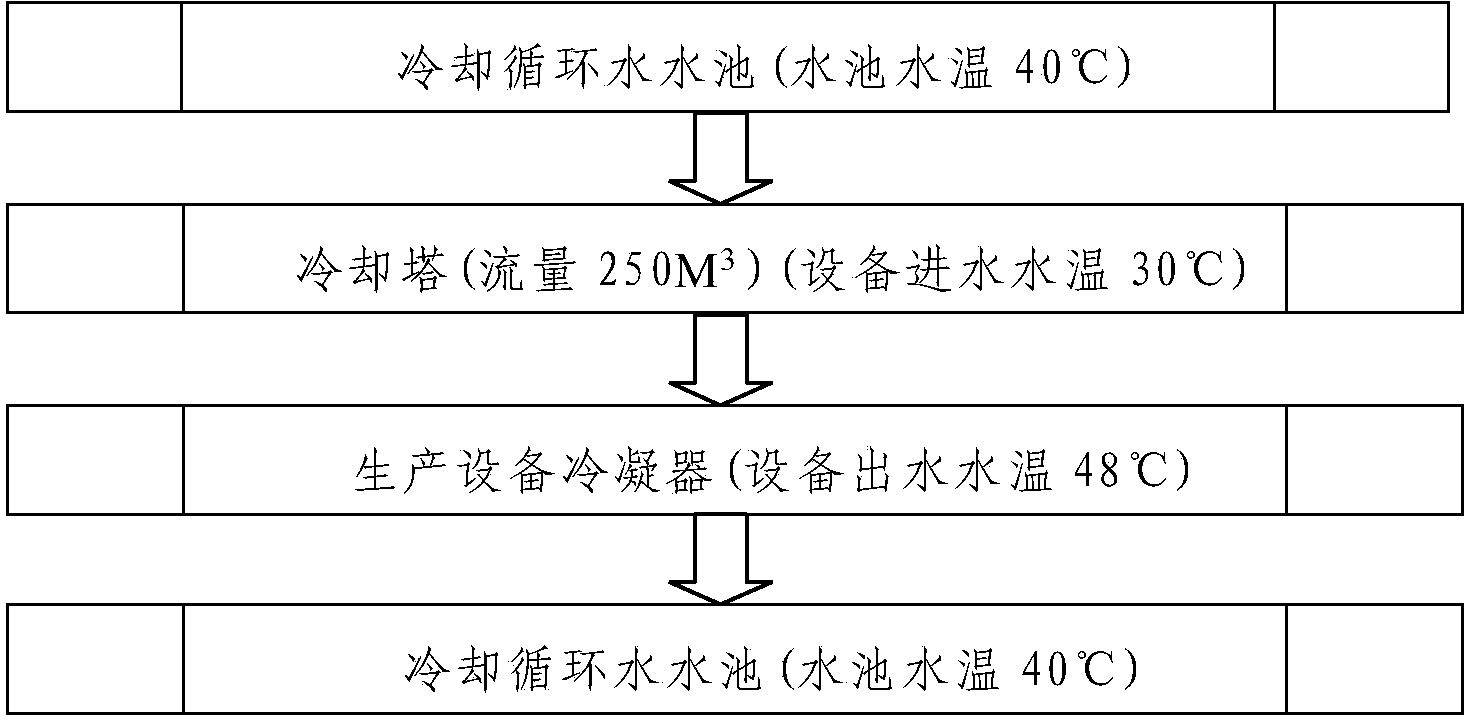
[0023] The technological process of the above-mentioned cooling circulating water system, such as Figure 4 shown, including the following steps:

[0024] A. The effluent from the circulating pool enters the condenser of the production equipment;

[0...


PUM


Abstract

The invention discloses a circulating water cooling system which is applied to water-cooled production equipment. The circulating water cooling system comprises a circulating water tank, a condenser of production equipment and a circulating water cooling device, which are sequentially and cyclically communicated with one another through pipelines, wherein circulating water cyclically flows in the circulating water tank, the condenser of the production equipment and the circulating water cooling device. The invention also discloses a technical flow of the circulating water cooling system. The technical flow comprises the following steps that A, water discharged by the circulating water tank enters the condenser of the production equipment; B, the water discharged by the condenser of the production equipment enters the circulating water cooling device; C, the water discharged by the circulating water cooling device reenters the circulating water tank, and the steps are repeated. According to the circulating water cooling system and the technical flow thereof which are disclosed by the invention, the productivity of the equipment can be improved, fuel oil can be saved, and the consumed energy such as water can be supplemented; therefore, the production cost of capital is greatly reduced.

Description

technical field [0001] The invention relates to the technical field of water cooling, in particular to a cooling circulating water system and a process flow thereof. Background technique [0002] With the rapid development of modern industry, the cooling circulating water system is used in the heat exchange process, the refrigerant fluid absorbs the heat of the production equipment to achieve the purpose of reducing the temperature, and has become an indispensable part of industrial production. [0003] The structure of the factory cooling circulating water system designed by the domestic national chemical and pharmaceutical design institute is as follows: figure 1 As shown, it includes a circulating water pool 1, a circulating pump 2, a cooling tower 5 (cooling device for circulating water), a circulating water tank 3 and a condenser 4 of the production equipment connected in sequence through pipelines, and the outlet pipe of the condenser 4 of the production equipment is c...

Claims


Application Information

Patent Timeline
Patent Type & Authority Applications(China)
IPC IPC(8): F25D17/02
Inventor 鲁兴礼
Owner DIHON PHARMA GROUP
Learn More