Failure analysis method for MIM capacitor

A technology of failure analysis and capacitance, which is applied in the manufacture of electrical components, semiconductor devices, semiconductor/solid-state devices, etc., can solve the problem that it is difficult to accurately determine the relative position of the leakage area of ​​the MIM capacitor, and achieve the effect of easy observation

Active Publication Date: 2013-11-20
SHANGHAI HUALI MICROELECTRONICS CORP
View PDF5 Cites 4 Cited by
  • Summary
  • Abstract
  • Description
  • Claims
  • Application Information

AI Technical Summary

Problems solved by technology

[0006] In the above-mentioned MIM capacitor device, the entire MIM capacitor is basically surrounded by the insulating medium, even if the insulating medium between the upper and lower plates has a leakage area, but because there is no leakage pa

Method used


Image

  • Failure analysis method for MIM capacitor
  • Failure analysis method for MIM capacitor
  • Failure analysis method for MIM capacitor

Examples


Example Embodiment

[0019] The specific embodiments of the present invention will be further described in detail below with reference to the accompanying drawings.

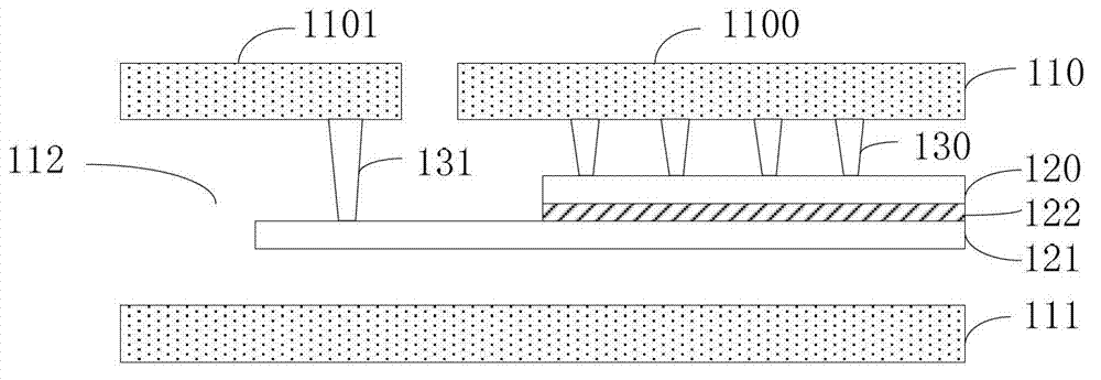
[0020] It should be noted that, in any embodiment of the present invention, the MIM capacitive device is located on a silicon substrate and is distributed in multiple layers. It includes at least an upper plate, a lower plate, and an upper plate and a lower plate. There are multiple metal layers vertically distributed on the silicon substrate, and a dielectric layer is filled between adjacent metal layers. Among them, the upper and lower plates can be one of the metal layers and are made of metal materials. It can also be formed between two adjacent metal layers and made of TiN or TaN material; the upper and lower electrode plates are respectively electrically connected to the first and second circuit regions of the first metal layer on the silicon substrate through Via wires. The above structure and figure 1 The structure of the MIM ca...


PUM


Abstract

The invention relates to a failure analysis method for an MIM capacitor. The MIM capacitor is positioned on a silicon substrate and comprises an upper pole plate, a lower pole plate and an insulating layer positioned between the upper pole plate and the lower pole plate. The silicon substrate also at least comprises a metal layer positioned above the MIM capacitor, and the upper pole plate and the lower pole plate are electrically connected with the first circuit region and the second circuit region of the metal layer respectively. The method comprises the following steps: (a) determining whether the lower pole plate is grounded or not, if not, performing a step (b); or else, performing a step (d); (b) looking for a power bus with the closest interlayer distance with the MIM capacitor; wherein the power bus comprises a grounding lead; (c) forming a circuit channel connecting the lower pole plate and the power bus; (d) by voltage contrast detection, determining the electric leakage area of the MIM capacitor. When the electric leakage area of the MIM capacitor is detected through voltage contrast, the condition of a smaller degree of electric leakage cannot be skipped, so that the method is convenient for observation and is more reliable.

Description

technical field [0001] The invention relates to the field of semiconductor processing and manufacturing, and more specifically, to a failure analysis method for a MIM capacitor device. Background technique [0002] The MIM (Metal-Insulator-Metal) capacitor structure is a capacitor structure formed between the interconnection layers of semiconductor devices, which is better compatible with the back-end process of semiconductor manufacturing. Therefore, it is widely used in CMOS processes such as radio frequency integrated circuits and semiconductor memories. [0003] In the MIM capacitor structure defined by two layers of photomasks, its basic structure is distributed from top to bottom as the first metal layer / intermetallic dielectric layer / MIM capacitor upper plate / MIM insulating layer / MIM capacitor lower plate / intermetallic Dielectric layer / second metal layer, where the upper and lower plates can be drawn out through Via (vertical through-hole interconnection technology) ...

Claims


Application Information

Patent Timeline
IPC IPC(8): H01L21/02H01L21/66H01L29/92G01R31/303
Inventor 孙转兰杨昌辉
Owner SHANGHAI HUALI MICROELECTRONICS CORP
Why Eureka
Try Eureka