led backlight short circuit protection circuit

A short-circuit protection circuit and backlight technology, which is applied in the direction of protection against overcurrent, can solve the problems of over-power consumption damage of circuit components, no automatic isolation protection, high price, etc., and achieve the effect of avoiding over-power consumption damage

Active Publication Date: 2016-04-27
GUANGZHOU SHIYUAN ELECTRONICS CO LTD
View PDF9 Cites 2 Cited by
  • Summary
  • Abstract
  • Description
  • Claims
  • Application Information

AI Technical Summary

Problems solved by technology

[0003] The solution is mature and highly reliable, but the price is too expensive to be widely used
Moreover, the existing LED backlight constant current scheme has no short-circuit protection, and there is no automatic isolation protection in the event of a short-circuit of the LED load, resulting in damage to the entire circuit element due to over-power consumption

Method used


Image

  • led backlight short circuit protection circuit
  • led backlight short circuit protection circuit
  • led backlight short circuit protection circuit

Examples


Embodiment Construction

[0033] Embodiments of the present invention will now be described with reference to the drawings, in which like reference numerals represent like elements.

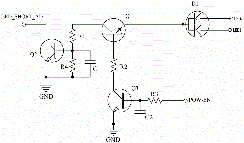
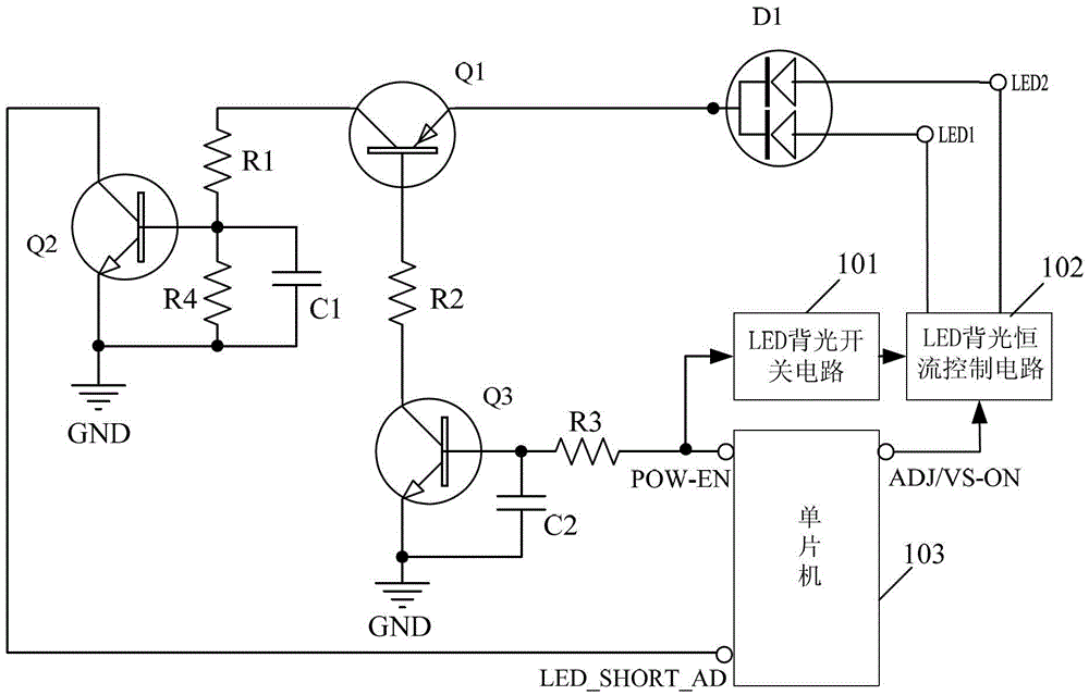
[0034] Please refer to figure 2 , is a circuit diagram of the first embodiment of the LED backlight short-circuit protection circuit of the present invention. The LED backlight short-circuit protection circuit includes a first transistor Q1, a second transistor Q2 and a third transistor Q3, wherein:

[0035] The emitter of the first triode Q1 is correspondingly connected to the cathode of the LED load through the diode D1 (it can be understood that when the LED load has only one way, the emitter of the first triode Q1 can be connected to the negative pole of the LED load without passing through the diode D1 directly connected to the load), the collector is grounded through the series resistors R1 and R4, and the connection point of the resistors R1 and R4 is connected to the base of the second transistor Q2, and the bas...


PUM


Abstract

The invention discloses an LED (light emitting diode) backlight short-circuit protection circuit, which comprises a first triode Q1, a second triode Q2 and a third triode Q3, wherein an emitting electrode of the first triode Q1 is connected to an LED load, a collector electrode of the first triode Q1 is grounded through a resistor R1 and a resistor R4 which are connected in parallel, the junction point of the resistor R1 and the resistor R4 is connected with a base electrode of the second triode Q2, and the base electrode is connected with a collector electrode of the third triode Q3 through a resistor R2; a collector electrode of the second triode Q2 is connected with a short-circuit protection end, and an emitting electrode is grounded; a base electrode of the third triode Q3 is connected with a control signal end through a resistor R3, and an emitting electrode is grounded; a constant output current is provided for the LED load by outputting high level to the control signal end, and the constant output current is not provided for the LED load by outputting low level to the control signal end; the short-circuit protection end and the control signal end are both connected onto a single-chip microcomputer; when the LED load is in short circuit, the second triode Q2 is connected, so that the short-circuit protection end outputs the low level, when the single-chip microcomputer detects that the short-circuit protection end is low-level, the low level is outputted to the control signal end, and the isolation protection can be realized.

Description

technical field [0001] The invention relates to the field of switching power supply circuits, and more particularly relates to an LED backlight short-circuit protection circuit. Background technique [0002] At present, in the application industry of switching power supply, especially in the application field of LED backlight TV, the mainstream constant current solution is mostly using BOOST boost circuit, that is, the front stage FLYBACK (or other architecture) outputs 12V (for power amplifier) ​​plus 24V (or other voltage levels), and then 24V again uses the second-stage BOOST constant current boost method, the structure diagram is as follows figure 1 Shown: After the AC input passes through the EMI filter circuit and bridge rectifier successively, and then passes through the pre-stage AC-DC voltage regulator circuit to output 12V voltage and 24V, and then the output 24V is first boosted and then BOOSTed to a constant current through a dedicated IC The working mode provid...

Claims


Application Information

Patent Timeline
Patent Type & Authority Patents(China)
IPC IPC(8): H02H3/08
Inventor 晁新库杨达富张碧原
Owner GUANGZHOU SHIYUAN ELECTRONICS CO LTD
Why Eureka
Try Eureka