
Wide range voltage adjustable buck-boost single-stage inverter circuit device

An inverter circuit and adjustable technology, applied in the direction of output power conversion devices, electrical components, and conversion equipment without intermediate conversion to AC, can solve the problem that the value cannot be increased, and achieve the reduction of passive components, small size, The effect of increasing noise immunity

Inactive Publication Date: 2013-11-20
QINGDAO TECHNOLOGICAL UNIVERSITY
View PDF3 Cites 8 Cited by
  • Summary
  • Abstract
  • Description
  • Claims
  • Application Information

AI Technical Summary

Problems solved by technology

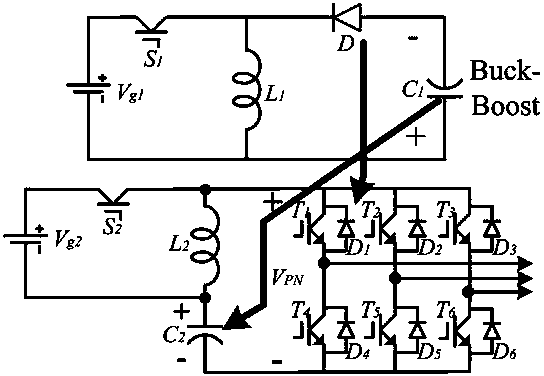
[0004] Among them, M is the modulation factor of the inverter. Since the value of M ranges from 0 to 1, the control circuit can control the on-off of the six IGBTs in the inverter by adjusting the modulation factor M, thereby controlling the output of the inverter. , but only by adjusting M to control the output of the inverter can only achieve the purpose of step-down control. Of course, according to the formula, it is also possible to increase V PN value to increase the output voltage, so if you need to output an AC voltage with a high effective value, you need to connect a higher DC voltage to the DC input of the inverter, but in some applications V PN cannot increase the value of

Method used


Image

  • Wide range voltage adjustable buck-boost single-stage inverter circuit device
  • Wide range voltage adjustable buck-boost single-stage inverter circuit device
  • Wide range voltage adjustable buck-boost single-stage inverter circuit device

Examples


Embodiment

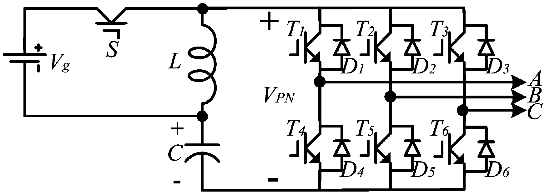
[0015] The main structure of this embodiment includes DC power supply Vg, switch tube S, inductor L, capacitor C and transistor T 1 ~T 6 with diode D 1 ~D 6 A three-phase voltage-type bridge inverter circuit formed in cooperation; one end of the switching tube S is electrically connected to the positive pole of the DC power supply Vg, the other end is electrically connected to one end of the inductor L, and the other end of the inductor L is electrically connected to the negative pole of the DC power supply Vg Electrically connected, a local loop is formed between the DC power supply Vg, the switching tube S and the inductor L; the positive pole of the electrolytic capacitor C and the inductor L are jointly connected to the negative pole of the DC power supply Vg, and form a three-phase voltage bridge inverter circuit A local loop; the three-phase voltage type bridge inverter circuit includes six bridge arms, each bridge arm is composed of an insulated gate bipolar transisto...


PUM


Abstract

The invention belongs to the technical field of electrical energy exchange, and relates to a wide range voltage adjustable buck-boost single-stage inverter circuit device. The device adopts the structure that one end of switch tube is electrically connected with a positive pole of a direct current supply, and the other end of the switch tube is electrically connected with one end of an inductor; one end of the inductor is electrically connected with the negative pole of the direct current supply; the positive pole of an electrochemical capacitor and the inductor are commonly connected with the negative pole of the direct current supply so as to form a local loop with a three-phase voltage type bridge-type inverter circuit which comprises six bridge arms, each bridge arm is composed of an isolated gate bipolar triode transistor and an antiparallel diode; the output end of the three-phase voltage type bridge-type inverter circuit are led out by three groups of mutually corresponding bridge arms; the three-phase voltage type bridge-type inverter circuit is the output end of the whole device and used for receiving the DC electric energy and outputting AC electric energy. The device has the advantages of good safety, less passive elements of the inverter circuit, small size, light weight, environmental protection, and wide voltage adjustable range.

Description

Technical field: [0001] The invention belongs to the technical field of electric energy exchange, and relates to a conversion circuit for converting direct current electric energy into alternating current electric energy, in particular to a buck-boost single-stage inverter circuit that can provide high-quality, good stability, and wide-range adjustable voltage for alternating current equipment device. Background technique: [0002] The inverter circuit is a conversion circuit that converts DC power into AC power. It can be used to form various AC power sources and is widely used in industry. The most common AC power supply in production is the public grid supplied by power plants (China adopts a power supply system with a line voltage root mean square value of 380V and a frequency of 50Hz). It is the most common way to supply power to AC loads from the public grid. However, with the development of production, quite a lot of electrical equipment has special requirements for ...

Claims


Application Information

Patent Timeline
IPC IPC(8): H02M7/5387H02M3/07
Inventor 丁新平
Owner QINGDAO TECHNOLOGICAL UNIVERSITY
Learn More