
Oil pump with selectable outlet pressure

An outlet port, pressure relief valve technology, applied in the direction of controlling the pressure of lubricants, components of pumping devices for elastic fluids, pump elements, etc., can solve problems such as high power consumption of oil pumps and reduced fuel efficiency

Active Publication Date: 2013-11-20
HANON SYST EFP CANADA LTD ONTARIO
View PDF9 Cites 15 Cited by
  • Summary
  • Abstract
  • Description
  • Claims
  • Application Information

AI Technical Summary

Problems solved by technology

[0007] Although such conventional oil pressure relief valves are simple and reliable, the work of the oil pump is difficult because the oil pump operates to increase the oil pressure to a preset pressure level even though a lower oil pressure may be suitable to provide satisfactory lubrication of the engine components. relatively high consumption
The high power consumption of the oil pump is equivalent to a decrease in fuel efficiency which is a disadvantage

Method used


Image

  • Oil pump with selectable outlet pressure
  • Oil pump with selectable outlet pressure
  • Oil pump with selectable outlet pressure

Examples


Embodiment Construction

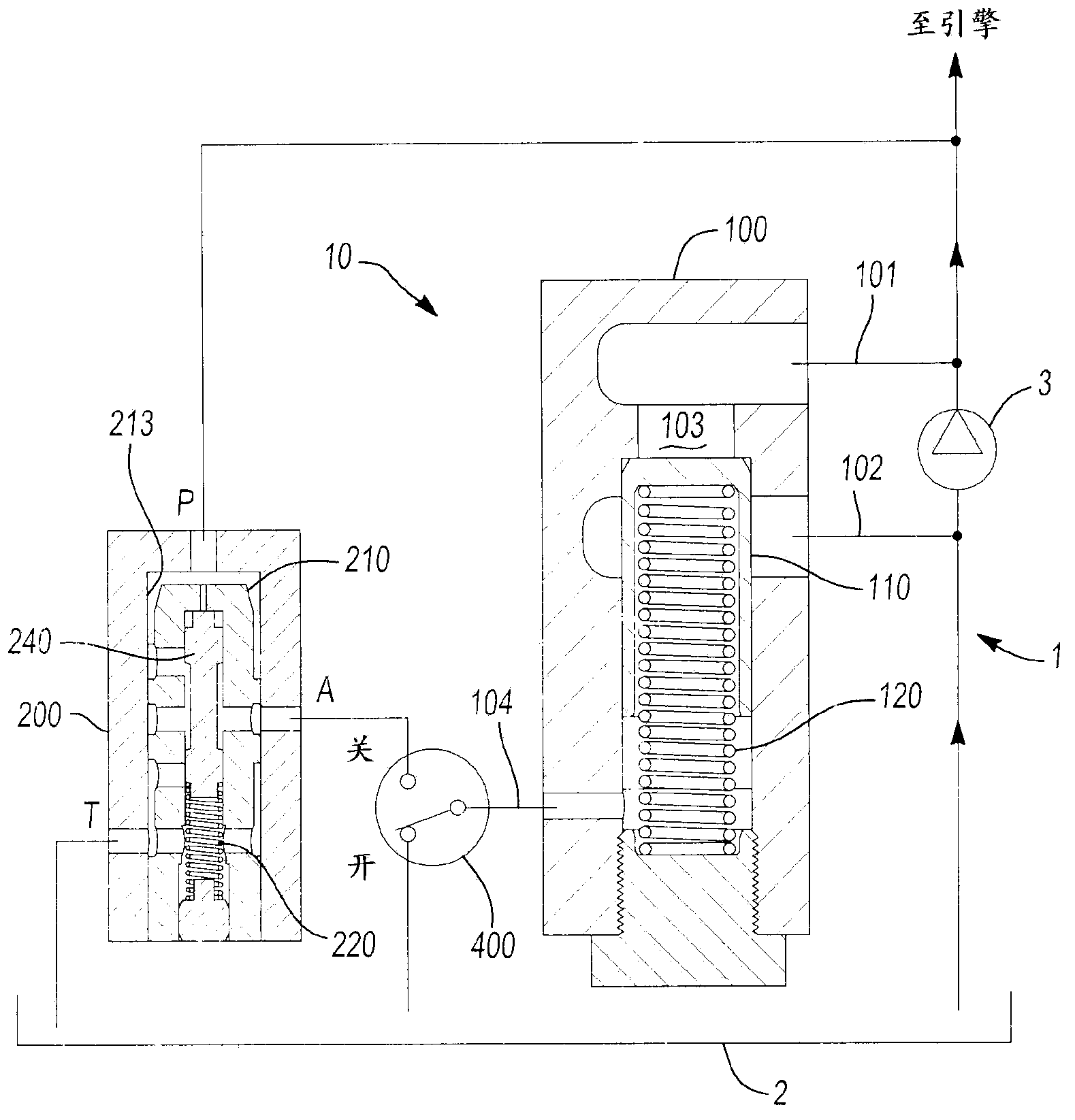
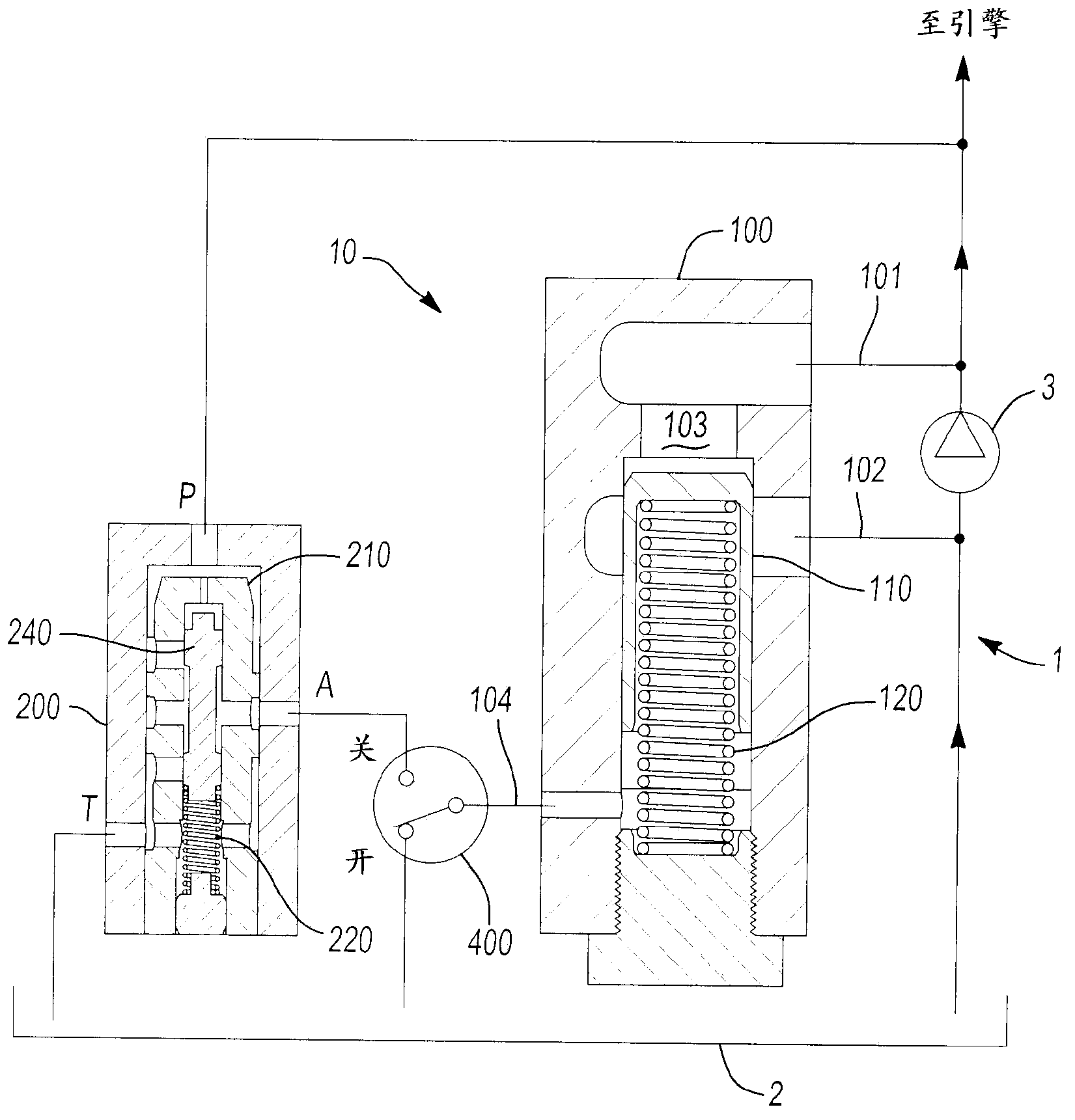
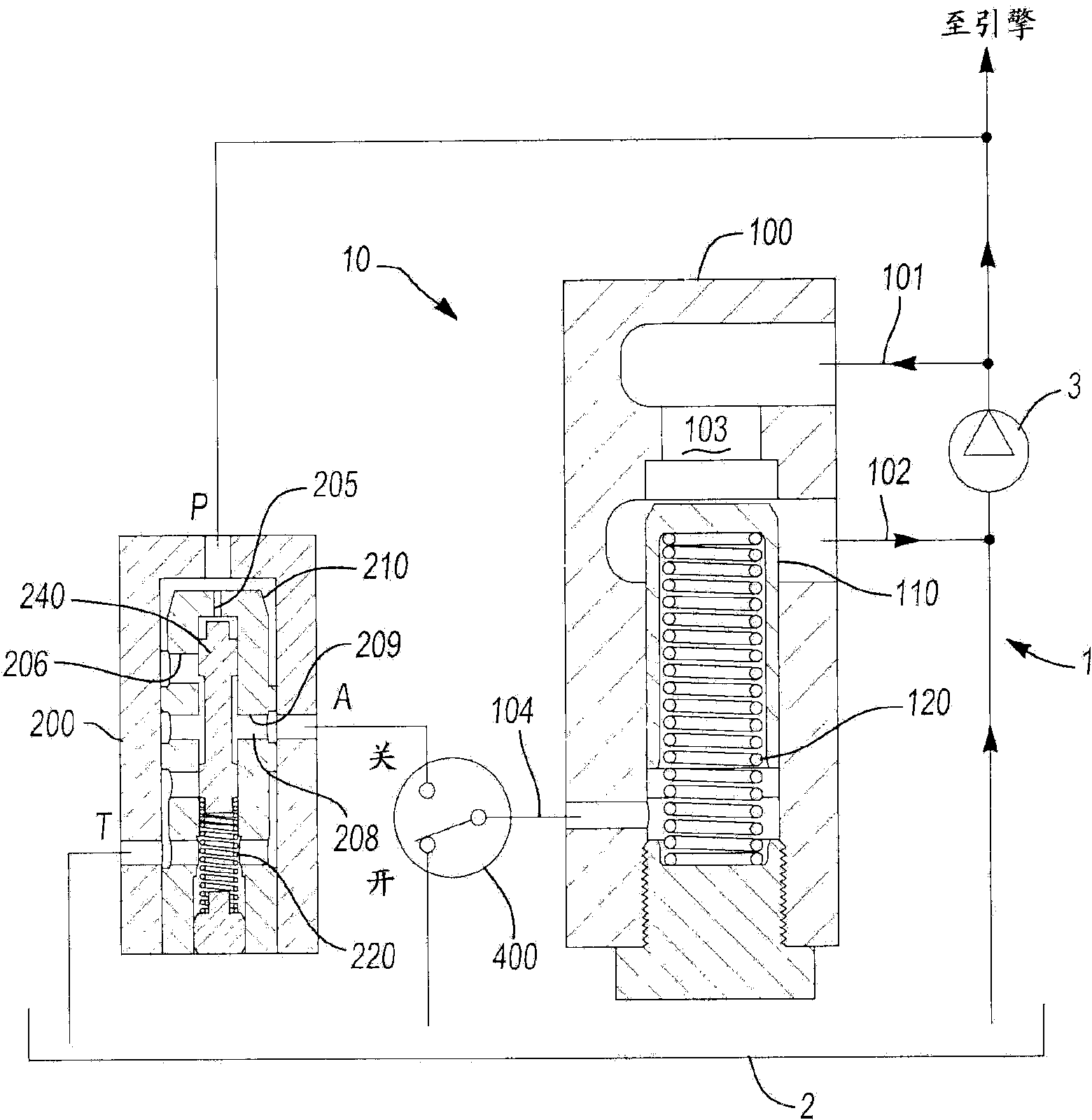
[0022] Referring generally to all figures, there is shown a schematic diagram of a pump system 1 including a pressure control system 10, and in figure 1 A pressure relief valve system 100 of such a pressure control system of a pump system 1 is shown in . The pump system 1 comprises a tank or container 2 schematically shown towards the bottom, and the working fluid is pumped from the container 2 by means of an oil pump 3 . The pump 3 may be a variable displacement type pump with a control feature that can vary the displacement of the pump 3 . But as will be appreciated by those skilled in the art, the pump 3 may be a fixed displacement pump in which a relief valve is provided as shown and its operating point or relief valve setting can be set as desired . The oil pump 3 is driven by the engine / engine or other means such as an electric motor (not shown), and when driven by the engine, the speed of the oil pump 3 varies with engine speed. As is known in the art, as the speed o...


PUM


Abstract

An oil pressure relief valve for use in the oil pump lubrication system of an internal combustion engine is controlled by both oil pump outlet pressure and by pilot pressure from a pilot valve which is selectively applied by a control member, preferably a two-way valve that is operated by the engine control module. The pilot valve selectively supplies one of the oil pump outlet pressure or the engine gallery pressure to the control member which selectively supplies pilot valve pressure to the oil pump pressure relief valve which has a single piston. The pilot valve includes first and second pistons for selectively controlling back pressure from the pressure relief valve and for managing changes in oil pressure due to changes in the engine gallery to maintain a virtually constant pressure even as oil pump speed increases when the control member connects the pilot valve to the pressure relief valve resulting in a fuel economy benefit and improved control of the oil pump pressure.

Description

[0001] Cross References to Related Applications [0002] This application claims priority and priority to U.S. Provisional Patent Application No. 61 / 437,365, entitled "OIL PUMP WITH SELECTABLE OUTLET PRESSURE," filed January 28, 2011 in the name of Williamson et al. Interest, the entire content of this application is incorporated herein by reference for all purposes. technical field [0003] The present disclosure generally relates to oil pump assemblies including pressure relief valves for managing oil pump discharge pressure and control valve pilot pressure. More specifically, the present disclosure relates to pressure relief valves having a pilot valve in communication therewith to find particular application in fixed displacement pump lubrication systems for internal combustion engines. Background technique [0004] It is generally known to provide an internal combustion engine that includes an oil pump assembly that pumps engine oil through the engine to pass through v...

Claims


Application Information

Patent Timeline
IPC IPC(8): F01M1/16F16N23/00F16N29/00F16N7/40
CPCF16N23/00F04B49/22F01M1/16F16N7/40F16N29/00F04B53/18
Inventor 马修·威廉森肯特·T·塔卡马楚-于尼瓦尔达雷尔·F·格林
Owner HANON SYST EFP CANADA LTD ONTARIO
Learn More