
Round Table Hammer Hole Making Machine

A technology of a rotary table hammer and a hole-making machine, which is applied to drilling equipment, earthwork drilling, and driving devices for drilling in boreholes. It can solve the problems of high power consumption and low efficiency, and achieve high impact efficiency and low power consumption. Effect

Active Publication Date: 2015-08-12
歌玛磨具南通有限公司
View PDF6 Cites 0 Cited by
  • Summary
  • Abstract
  • Description
  • Claims
  • Application Information

AI Technical Summary

Problems solved by technology

[0002] At present, the drilling machines used in drilling engineering are powered on the ground, and the impact drill bit is lifted to a certain height by the hoist through the oil wire rope and then landed to impact the formation to create holes. In this way, the power consumption is large and the efficiency is low.

Method used


Image

  • Round Table Hammer Hole Making Machine
  • Round Table Hammer Hole Making Machine

Examples


specific Embodiment

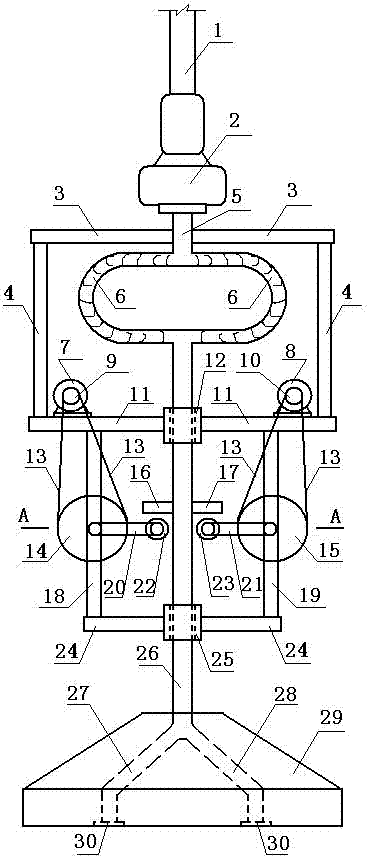
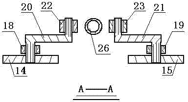
[0012] Accompanying drawing is a kind of concrete embodiment of the present invention, and this embodiment drilling rod 1 lower end is connected with mud pump 2, and mud pump lower end is connected with suction pipe A5, and suction pipe A is fixed in the middle of cross arm A3, cross arm A, cross arm B11, Cross arm C24, two longitudinal arms A4, longitudinal arm B18, and longitudinal arm C19 are welded into a stable steel structure. The lower end of suction pipe A is connected to the upper end of suction pipe B26 through two curved corrugated tubes 6. Suction pipe B passes through sleeve A12, sleeve B25, the lower end of the suction pipe B is connected with the suction pipe C27 and the suction pipe D28, and the lower end of the suction pipe B is also fixed with a round table hammer 29; The end cover is equipped with a wheel A22, the upper part of the wheel A is provided with a handle rod A16, the handle rod A is fixed on the left side of the suction pipe B, and the crank arm B2...


PUM


Abstract

Disclosed is a cone frustum hammer pore-forming machine. The lower end of a drill rod is connected with a slurry pump, the lower end of the slurry pump is connected with a suction pipe, the suction pipe is fixed in the middle of a transverse arm A, the transverse arm A, a transverse arm B, a transverse arm C, two longitudinal arms A, a longitudinal arm B and a longitudinal arm C are welded to form a stable steel structure, the lower end of the suction pipe is connected to the upper end of a suction pipe B through two bent corrugated pipes, the suction pipe B penetrates a sleeve A and a sleeve B, the lower end of the suction pipe B is connected with a suction pipe C and a suction pipe D and also fixed to a cone frustum hammer, a crank arm A is arranged in the middle of the longitudinal arm B, a driven belt pulley A is fixed to a shaft end on one side of the crank arm A, a wheel A is sleeved at a shaft end on the other side of the crank arm A, the upper portion of the wheel A is provided with a handle lever A, the handle lever A is fixed to the left of the suction pipe B, a crank arm B is arranged in the middle of the longitudinal arm C, a driven belt pulley B is fixed to a shaft end on one side of the crank arm B, a wheel B is sleeved at a shaft end on the other side of the crank arm B, the upper portion of the wheel B is provided with a handle lever B, and the handle lever B is fixed to the right of the suction pipe B.

Description

technical field [0001] The invention relates to a hole making machine, in particular to a circular table hammer hole making machine used in drilling engineering. Background technique [0002] At present, the hole-making machines used in the drilling engineering are powered on the ground, and the impact drill bit is lifted to a certain height by the oil wire rope with the hoist and then landed to impact the formation to make holes. In this way, the power consumption is large and the efficiency is low. Contents of the invention [0003] The present invention makes up for the above shortcomings and provides a circular table hammer hole making machine. [0004] The present invention is achieved through the following technical solutions: [0005] A circular table hammer drilling machine, the lower end of the drill pipe is connected with a mud pump, the lower end of the mud pump is connected with a suction pipe, the suction pipe is fixed in the middle of the cross arm A, cross ...

Claims


Application Information

Patent Timeline
Patent Type & Authority Patents(China)
IPC IPC(8): E21B4/12
Inventor 王和林张璐
Owner 歌玛磨具南通有限公司
Learn More