Floating sea wave power generation device with force-amplifying mechanisms

A booster mechanism and wave power generation technology, which is applied in ocean energy power generation, machines/engines, mechanical equipment, etc., can solve problems such as energy consumption, high cost, and large size of key parts, so as to reduce maintenance costs, increase service life, The effect of reducing pollution

Inactive Publication Date: 2013-11-27
CHINA FIRST HEAVY IND
View PDF9 Cites 10 Cited by
  • Summary
  • Abstract
  • Description
  • Claims
  • Application Information

AI Technical Summary

Problems solved by technology

[0002] After searching the existing technology, it is found that the fan-shaped tank wave power generation device that converts the impact energy of waves into electric energy (Chinese Patent No. ZL. The construction process of the tank is limited by the terrain and affected by the ebb and flow, so the construction difficulty and engineering volume are quite large
2. The fan-shaped tank is located on the shore. When the waves finally reach the device, a lot of energy has been consumed, so the efficiency of the device to generate electricity using wave energy is low
3. After the tide rises, the swing ability of the fan-shaped buoy decreases, and the wave power cannot be effectively used in the process
The main shaft finally transmits the movement to the generator to realize power generation, but the device has the following disadv

Method used


Image

  • Floating sea wave power generation device with force-amplifying mechanisms
  • Floating sea wave power generation device with force-amplifying mechanisms
  • Floating sea wave power generation device with force-amplifying mechanisms

Examples


Embodiment 1

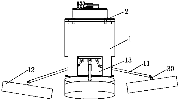
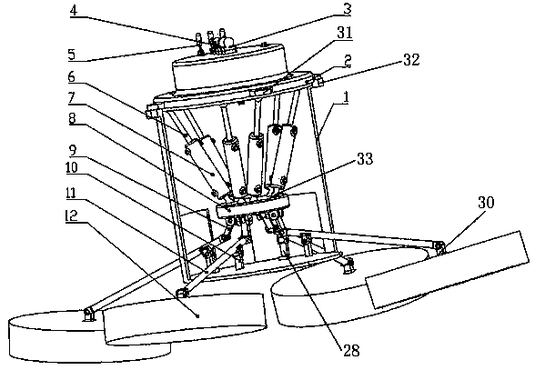
[0035] A floating wave power generation device with a booster mechanism, including a buoy device, a hydraulic cylinder device, a fuel tank 2, a hydraulic motor 4, a generator 3, a connecting platform 8, an outer cylinder 1 and a booster device, and the hydraulic motor 4 includes The hydraulic motor oil inlet, the hydraulic motor oil outlet, the rotating shaft and the base 29, the hydraulic motor 4 and the generator 3 are connected through the rotating shaft, and the base 29 is located on the upper part of the oil tank 2;

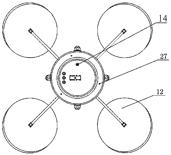
[0036] The fuel tank 2 is a cylindrical fuel tank with protruding eaves, and its upper part is provided with a fuel tank oil return port 14. The oil outlet of the hydraulic motor 4 is connected to the oil return port of the fuel tank 2 for the oil return of the entire oil circuit. The bottom of the protruding eaves There is a stopper, the side wall of the protruding eaves is radially provided with a fuel tank protruding platform 31, and the protruding eaves a...

Embodiment 2

[0045] Embodiment 2 is a modification of Embodiment 1. On the basis of Embodiment 1, this embodiment also includes an accumulator 5 , which is arranged on the upper part of the oil tank 2 and connected with the hydraulic motor 4 . At this time, the top of the oil tank 2 is also provided with a circular protruding platform for installing the accumulator 5, and the diameter of the circular protruding platform is consistent with the diameter of the accumulator base.

Embodiment 3

[0047] Embodiment 3 is a modification of Embodiment 1 and / or Embodiment 2. The main difference is that the inner diameter of the outer cylinder body 1 is the same as the outer diameter of the protruding eaves, and the top side of the outer cylinder body 1 is radially provided with a protruding platform similar to that of the fuel tank. 31 Outer cylinder protrusions 32 with the same number, the connection between the fuel tank 2 and the outer cylinder 1 is connected by bolts through the fuel tank protrusions 31 and the outer cylinder protrusions 32 .

[0048] The working principle of the present invention is as follows: the present invention is fixed on the fixed support as a whole, and the fixed support is fixed on the seabed. The waves impact the buoy device, pushing the buoy device to move upward; when the sea wave recedes, the buoy device resets under the action of its own gravity. During the up and down movement of the float device, the booster device drives six hydraulic ...


PUM


Abstract

The invention relates to a floating sea wave power generation device with force-amplifying mechanisms. The floating sea wave power generation device comprises an outer barrel, a floater device, a force-amplifying device, a hydraulic cylinder device, an oil tank, a hydraulic motor and a power generator, wherein the force-amplifying device is arranged on the floater device, the oil tank is arranged on the hydraulic cylinder device, and the hydraulic motor and the power generator are arranged on the oil tank and connected with each other; the floater device comprises four floating bodies, the hydraulic cylinder device comprises six hydraulic cylinders arranged in parallel, one ends of the hydraulic cylinders are hinged to the bottom of the oil tank, and the other ends of the hydraulic cylinders are connected with the force-amplifying device through a connection platform; the outer barrel is arranged on the lower portion of the oil tank, and the hydraulic cylinder device is sleeved with the outer barrel; the force-amplifying device comprises four force-amplifying mechanisms, each force-amplifying mechanism comprises a lever, a connection rod and a supporting rod, one end of each supporting rod is connected to the upper portion of the bottom of the outer barrel, the other end of each supporting rod is connected to the fulcrum of each lever, one end of each lever is connected to one end of each connection rod, the other end of each lever is connected to each floating body, and the other end of each connection rod is connected to the lower portion of the connection platform. The floating sea wave power generation device makes full use of sea wave energy and enhances power generation capability.

Description

technical field [0001] The invention relates to a floating ocean wave power generation device, in particular to a floating ocean wave power generation device with a booster mechanism. Background technique [0002] After searching the existing technology, it is found that the fan-shaped tank wave power generation device that converts the impact energy of waves into electric energy (Chinese Patent No. ZL. The construction process of the tank is limited by the terrain and affected by the ebb and flow of the tide, so the construction difficulty and engineering volume are quite large. 2. The fan-shaped water tank is located on the shore base. When the waves finally reach the device, a lot of energy has been consumed, so the efficiency of the device to generate electricity using wave energy is low. 3. After the high tide, the swing ability of the fan-shaped buoy decreases, and the wave power cannot be effectively used in the process. [0003] Investigate the existing swing-type ...

Claims


Application Information

Patent Timeline
IPC IPC(8): F03B13/16
CPCY02E10/38Y02E10/30
Inventor 马春翔高峰郑茂琦何俊任晖
Owner CHINA FIRST HEAVY IND
Why Eureka
Try Eureka