
Quantitative air distribution economic combustion energy saving control system

An energy-saving control system and economical combustion technology, applied in the direction of combustion method, combustion control, fuel supply adjustment, etc., can solve the problem of not considering the boiler structure and combustion process, coal type, calorific value, air intake volume, environmental pollution, etc. problem, to achieve the effect of improving the overall work efficiency

Inactive Publication Date: 2013-11-27
柳州市泰尔热能环保科技有限公司
View PDF4 Cites 7 Cited by
  • Summary
  • Abstract
  • Description
  • Claims
  • Application Information

AI Technical Summary

Problems solved by technology

[0003] The traditional boiler control method is to use baffles or valves to manually control the flow rate of the drum, induced draft fan, water supply pump, and circulating water pump, without considering the boiler structure and combustion process, coal type, calorific value, air intake and other factors
In addition, due to different production processes and production tasks, when the demand for steam and water temperature changes, the amount of coal feed and air distribution needs to be changed to achieve high-efficiency combustion. polluted environment

Method used


Image

  • Quantitative air distribution economic combustion energy saving control system
  • Quantitative air distribution economic combustion energy saving control system
  • Quantitative air distribution economic combustion energy saving control system

Examples


Embodiment 1

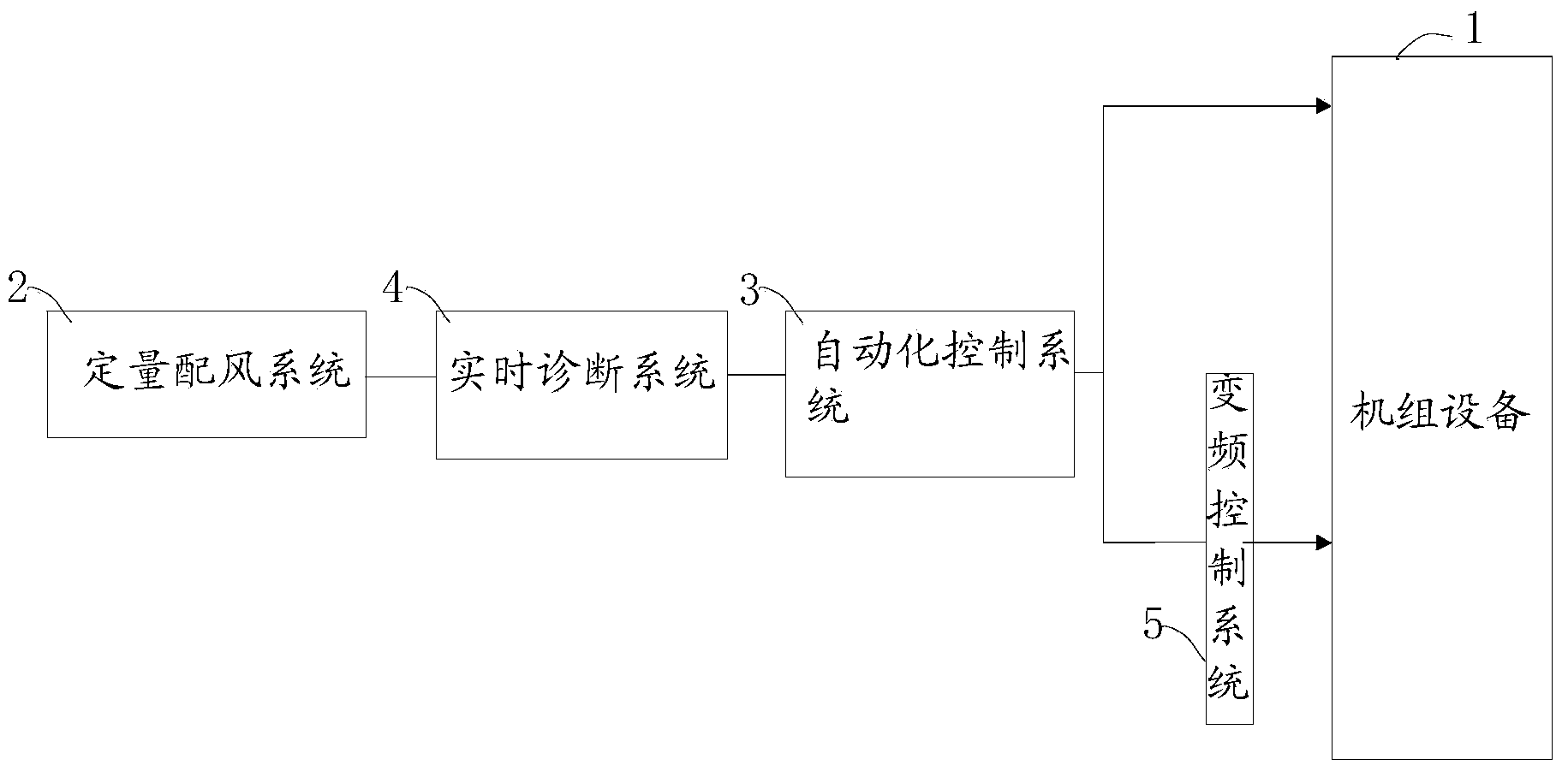
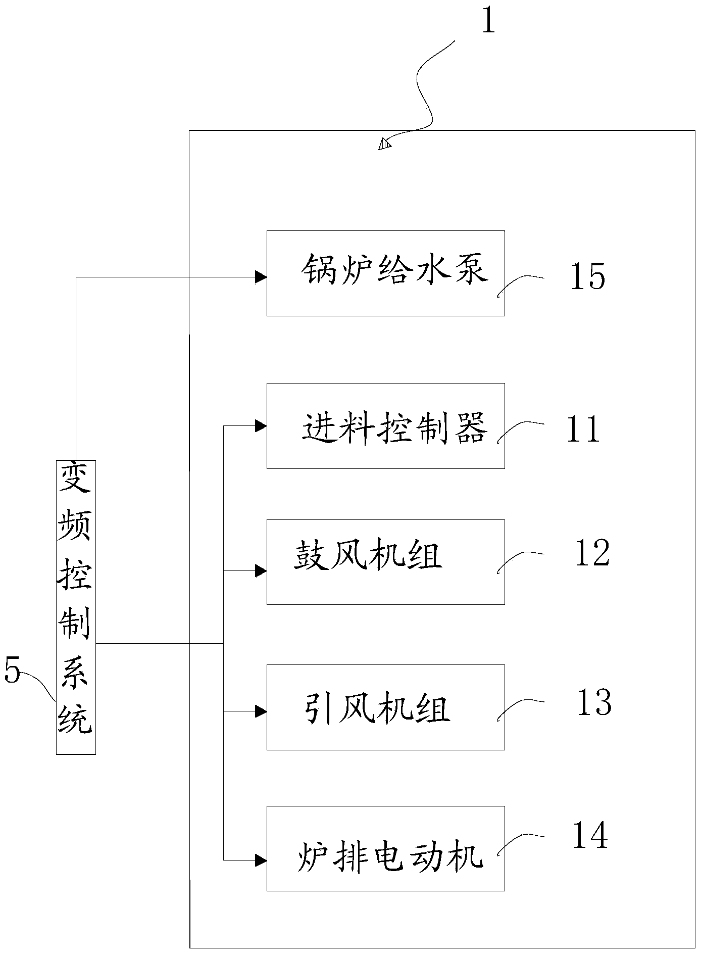
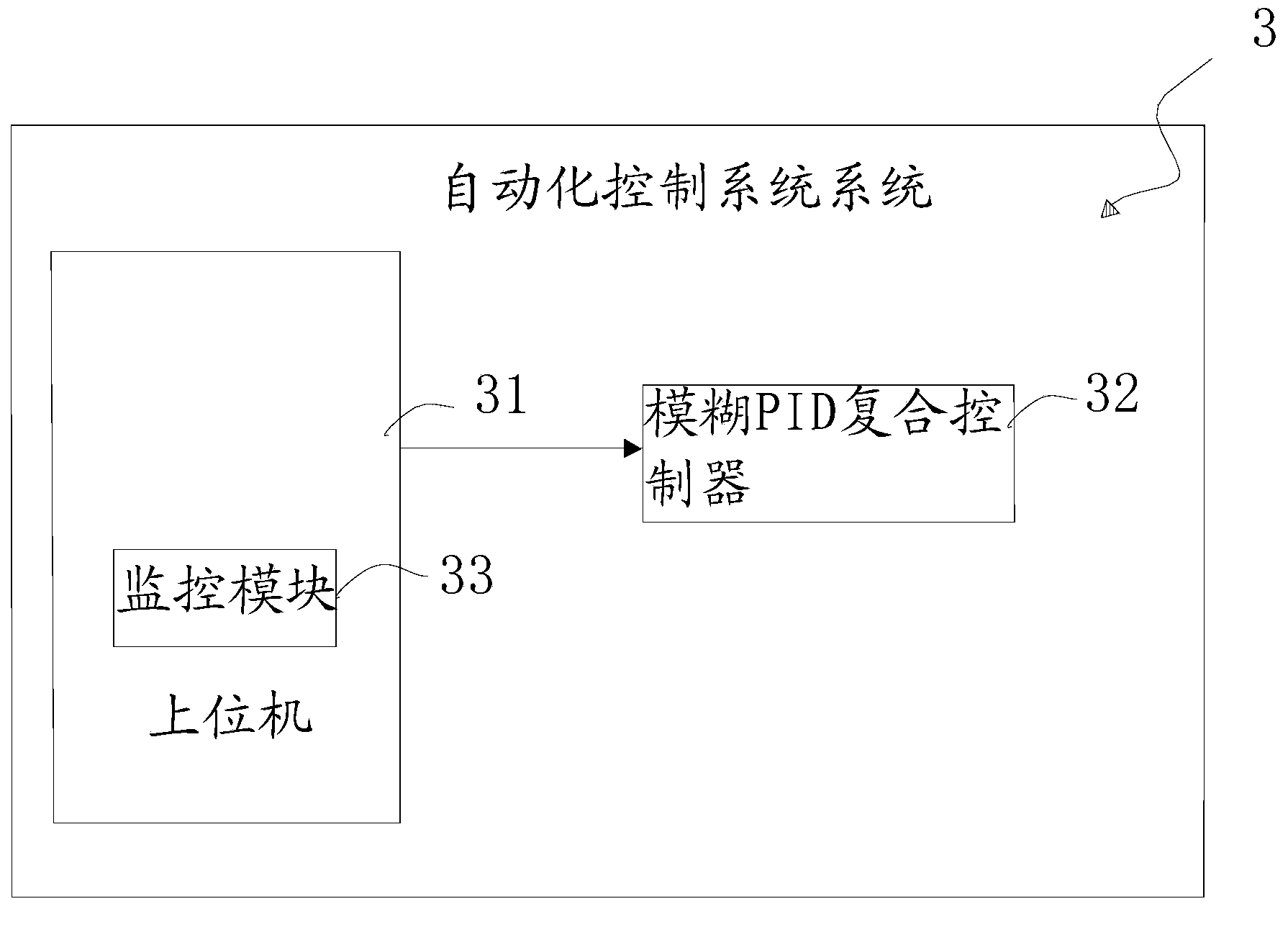
[0020] as attached Figure 1 to Figure 3 As shown, Embodiment 1 of the present invention provides a quantitative air distribution economical combustion energy-saving control system, including unit equipment 1, such as figure 2 As shown, the unit equipment 1 includes a feed controller 11, a blower unit 12, an induced draft unit 13, a grate motor 14, and a boiler feed water pump 15, and also includes a quantitative air distribution system 2 electrically connected to the unit equipment 1, an automatic Control system 3 and real-time diagnosis system 4;

[0021] The quantitative air distribution system 2 is used to control the speed of the blower unit 12, the induced draft unit 13 and the grate motor 14 of the unit equipment 1 to reach a reasonable ratio;

[0022] The real-time diagnosis system 4 is used to receive the boiler performance parameters sent by the automatic control system and obtain the optimal control scheme through analysis and calculation, and generate and send ad...


PUM


Abstract

The invention discloses a quantitative air distribution economic combustion energy saving control system. The quantitative air distribution economic combustion energy saving control system comprises a machine set device which comprises a feeding controller, a blower assembly, an induced fan assembly, a grate motor and a boiler feed pump. The quantitative air distribution economic combustion energy saving control system also comprises a quantitative air distribution system, an automatic control system and a real-time diagnosis system which are electrically connected with the machine set device; the quantitative air distribution system is used for controlling the rotating speed of the blower assembly, the induced fan assembly and the grate motor of the machine set device to achieve a reasonable ratio; the real-time diagnosis system is used for receiving boiler performance parameters which is sent from the automatic control system, obtaining an optimal control scheme after analysis and calculation, generating into a regulation control command according to the optimal control scheme and sending the regulation control command; the automatic control system is used for monitoring the machine set device to obtain the boiler performance parameter, receiving the regulation control command and performing distributed logic control and process control on the machine set device. The quantitative air distribution economic combustion energy saving control system has the advantages of being efficient, energy saving and environmentally friendly, enabling the service life of the boiler and ancillary facilities of the boiler to be prolonged and being high in safety performance.

Description

technical field [0001] The invention relates to boiler energy-saving equipment, in particular to a quantitative air distribution economical combustion energy-saving control system. Background technique [0002] Boiler is a kind of energy conversion equipment. The energy input to the boiler is in the form of chemical energy in fuel, electric energy, heat energy of high-temperature flue gas, etc. After conversion by the boiler, it outputs steam, high-temperature water or organic heat carrier with certain heat energy. . The hot water or steam generated in the boiler can directly provide the required heat energy for industrial production and people's life, and can also be converted into mechanical energy through a steam power plant, or converted into electrical energy through a generator, which is used in thermal power stations, ships, locomotives And industrial and mining enterprises have a very wide range of applications. [0003] The traditional boiler control method is to ...

Claims


Application Information

Patent Timeline
IPC IPC(8): F23N1/10
Inventor 罗泽云蓝登科莫小清辜程张兴区
Owner 柳州市泰尔热能环保科技有限公司
Learn More