Opening side skirt plate type on-duty flame stabilizer

A flame stabilizer and stabilizer technology, which is applied in the combustion method, combustion chamber, combustion equipment and other directions, can solve the problems of uneven temperature field of the stabilizer, high temperature in the recirculation zone, low temperature on both sides, etc., and achieves simple structure and flame. The effect of short length and uniform temperature field

Active Publication Date: 2013-11-27
BEIHANG UNIV
View PDF4 Cites 10 Cited by
  • Summary
  • Abstract
  • Description
  • Claims
  • Application Information

AI Technical Summary

Problems solved by technology

[0006] The technical problem mainly solved by the present invention is: the combustion reaction of the traditional blunt body flame stabilizer is concentrated in the recirculation zone, so the temperatur

Method used


Image

  • Opening side skirt plate type on-duty flame stabilizer
  • Opening side skirt plate type on-duty flame stabilizer
  • Opening side skirt plate type on-duty flame stabilizer

Examples


Embodiment 1

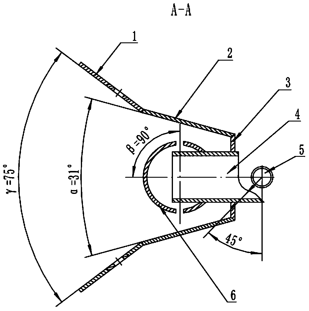
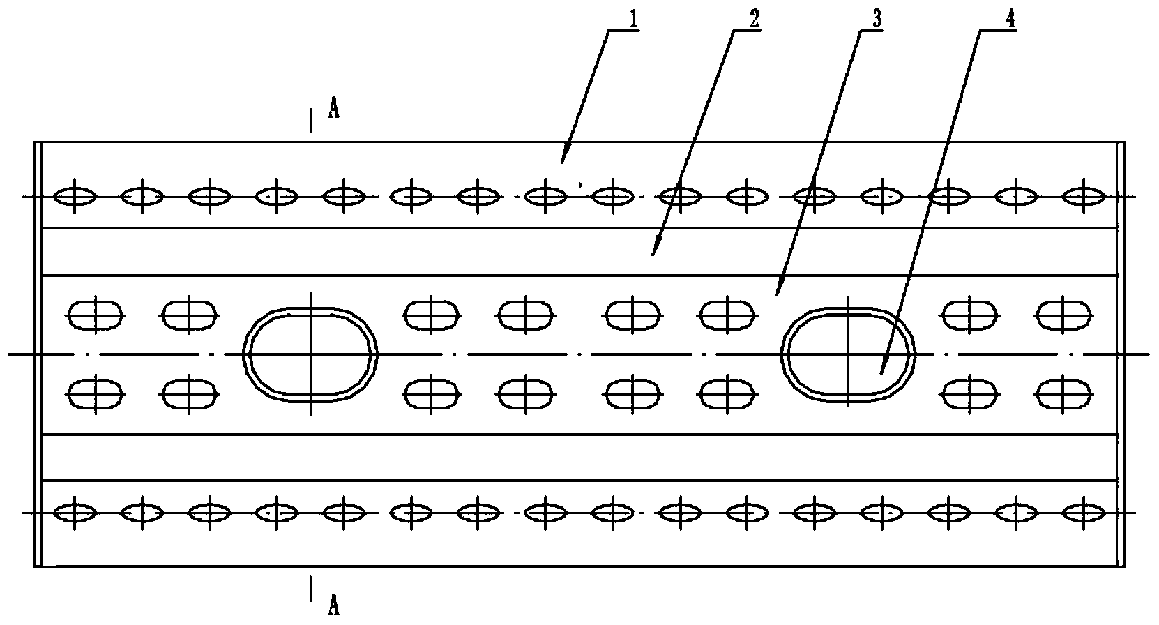
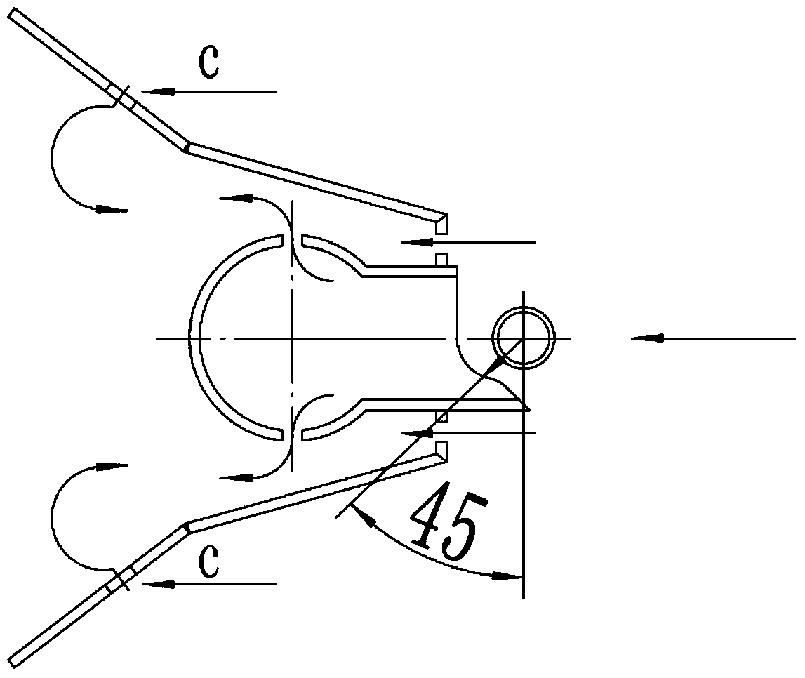
[0027] figure 1 , figure 2 It is a structural representation of the present invention. A perforated side apron type duty flame stabilizer of the present invention comprises a stabilizer perforated side apron 1, a stabilizer side plate 2, a stabilizer head panel 3, a stabilizer fuel distribution pipe intake pipe 4, and a direct injection rod 5 and stabilizer fuel distribution pipe 6.

[0028] figure 1 is a cross-sectional view, such as figure 1 , Stabilizer opening side skirt plate 1, stabilizer side plate 2, stabilizer head panel 3, stabilizer fuel distribution pipe 6, stabilizer fuel distribution pipe air inlet 4 is welding relationship, the fuel supply scheme is to adopt a A two-hole direct injection rod 5, on which there is a fuel injection hole with a diameter of 0.7 mm, the position of the fuel injection hole corresponds to the fuel distribution pipe intake pipe 4 of the flame stabilizer on duty, and the position of the fuel injection hole The direction of fuel inje...

Embodiment 2

[0047] To open holes on the skirt plates on both sides of the stabilizer, two parameters need to be determined: one is the position of the hole; the other is the area of ​​the hole. Different opening positions will cause different air mixing positions, which will have different effects on the flow field in the stable area behind the stabilizer, and then affect the combustion performance. Different opening areas determine the amount of air introduced. Different The amount of bleed air will affect the mixing effect on the rear temperature field, and will also affect the uniformity of the temperature field behind the stabilizer.

[0048] Two flame stabilizers with different structures are designed, and the specific design parameters of these two flame stabilizers are introduced in detail below.

[0049] The side skirt plate type flame stabilizer with openings proposed by the present invention has the same structural parameters in the part except the skirt plate: groove width, flo...


PUM


Abstract

The invention relates to an opening side skirt plate type on-duty flame stabilizer. According to the stabilizer, a row of bleed air holes are formed in two side skirt plates of the stabilizer, an airflow is introduced for supplementing and blending air in a central area after ignition of the flame stabilizer, so that the core temperature of the airflow is reduced, the temperatures of two sides are increased, and the purpose of improving the uniformity of temperature field is achieved finally; and meanwhile, the introduced airflow can be blended with unburned fuels for combustion, thus the purpose of improving the combustion efficiency of the stabilizer is achieved. According to the stabilizer, the uniformity of the temperature field behind the flame stabilizer and the combustion efficiency can be effectively improved, while the traditional bluff-body flame stabilizer is small in flame width and poor in temperature uniformity.

Description

technical field [0001] The invention relates to the technical field of blunt body flame stabilizers, in particular to a perforated side skirt type duty flame stabilizer. The device has a stabilizer perforated side skirt on the upper and lower sides of the stabilizer. , Compared with the traditional blunt body flame stabilizer, the device can better improve the outlet temperature distribution of the combustion chamber, improve the combustion efficiency, and shorten the flame length. Background technique [0002] The afterburner is a device that uses the principle of reburning to ignite the gas behind the turbine by injecting fuel, and uses the remaining oxygen in the gas to burn again to increase the temperature of the airflow and increase the jet velocity, thereby increasing the thrust of the engine in a short period of time. For all types of contemporary fighter engines, the afterburner is a necessary and important part. After the afterburner is activated, the total thrust ...

Claims


Application Information

Patent Timeline
IPC IPC(8): F23R3/20
Inventor 刘玉英郭庆波张文龙周冠宇金捷季鹤鸣
Owner BEIHANG UNIV
Why Eureka
Try Eureka