A Digital Wavelength Coded Optical Absolute Displacement Sensor

An absolute displacement sensor technology, applied in the field of displacement sensor, to simplify the demodulation system and improve the response frequency

Active Publication Date: 2016-03-02
UNIV OF SCI & TECH OF CHINA
View PDF5 Cites 0 Cited by
  • Summary
  • Abstract
  • Description
  • Claims
  • Application Information

AI Technical Summary

Problems solved by technology

There is no displacement sensor using this method and structure

Method used


Image

  • A Digital Wavelength Coded Optical Absolute Displacement Sensor
  • A Digital Wavelength Coded Optical Absolute Displacement Sensor
  • A Digital Wavelength Coded Optical Absolute Displacement Sensor

Examples


Embodiment 1

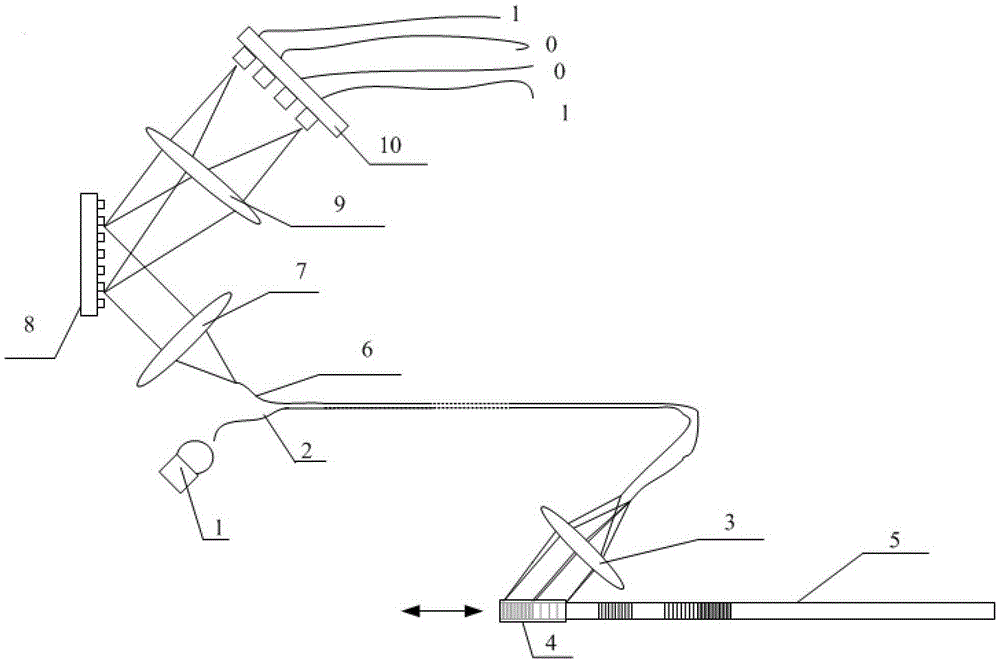
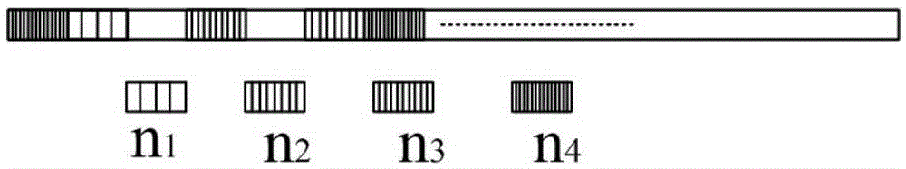
[0055] Taking the four-digit coded grating ruler as an example, the size of the grating unit is 100μm×1.5mm (1.5mm along the direction of the grating line), and the width of the grating ruler is 1.5mm. For the structure of the grating ruler, see Image 6 As shown, the relationship between the code combination and displacement of the demodulation system is shown in Table 1.

[0056] The size of the aperture is 0.3mm×2mm, the four sets of gratings of the grating scale are 1200lines / mm(n4), 1071lines / mm(n3), 968lines / mm(n2), 882lines / mm(n1), the four sets of gratings are Collimated diffraction wavelengths are: 500nm, 560nm, 620nm and 680nm. The light source is a halogen tungsten light source with a bandwidth of 400-1000nm. It is transmitted through the optical fiber 2 and then collimated by the collimator lens 3. After passing through the diaphragm 4, it is incident on the grating scale 5 with an incident angle of 17.46°. The diffracted light passes through the light again. Stop...

Embodiment 2

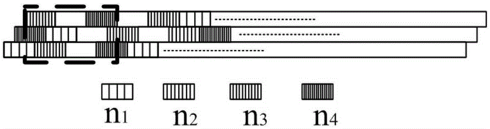
[0060] Take the "three-point" four-digit coded grating scale as an example. The grating scale is divided into three areas. The grating unit size of each area is 300μm×2mm, and the width of the grating scale is 6mm. The width of the grating ruler is 2mm, and the aperture is also divided into three areas. The structure of the grating ruler is shown in Figure 7 shown. The coding misalignment between the grating units in the three areas is 100 μm, that is, Figure 7 Shown: Codes appear at 0.1mm, 0.2mm, and 0.3mm respectively on the gratings of C area, B area, and A area. The relationship between the code combination and the displacement of the demodulation system is shown in Table 2.

[0061] Table 2

[0062]

[0063]

[0064] The aperture size is 0.9mm×7mm, divided into three areas, such as Figure 7 The three areas A, B, and C are shown. The size of A area and C area is 0.9mm×2.5mm, and the size of B area is 0.9mm×2mm. The diaphragm partitions strictly correspond to t...

Embodiment 3

[0066] The width of the grating ruler is 8mm, and it is divided into 4 areas. The size of the grating unit in each area is 200μm×2mm (2mm along the direction of the grating line). The grating units in the 4 areas are dislocated, and the dislocation amount is 50μm. The grating ruler contains a total of four groups of different grating line densities, which are 1250lines / mm, 1091lines / mm, 967.7lines / mm, and 870lines / mm. The blaze angle of the grating is 17.5°, and the incident light includes a combined light source of four groups of light sources with center wavelengths of 480, 550, 620, and 690nm and full width at half maximum greater than 10nm. The incoming part of the light source is guided by a 400μm optical fiber, and the receiving part uses 4 optical fibers corresponding to the 4 areas of the grating scale. After the incident light passes through the transmission fiber, it becomes parallel light through the collimating lens (focal length: 9mm, aperture: 6mm), and an apertu...


PUM


Abstract

The invention provides a digital wave length coding optical absolute displacement sensor. An incidence light spot enters a coding grating ruler to obtain a wave band coding signal, the wave band coding signal is demodulated to be converted into a digital electrical signal, and the one-to-one relationship between the displacement and wave length codes is built. A demodulating system directly gives out a digital signal, microminiaturization processing of the demodulating system is facilitated, a sensor part and a signal transmission part are both in optical signal transmission, and anti-electromagnetic interference can be achieved. Whether the signal exists or not is judged according to different kinds of wave length information and does not depend on the strength information of the optical signal, the problem of error codes caused by signal intensity changes generated by vibration, optical fiber transmission losses and light source intensity fluctuation is solved, compared with a wave length coding sensor adopting a grating distance variable optical grating at present, the digital wave length coding optical absolute displacement sensor has the advantages that a continuous light source is not required, a color sensing element with large light sensing area is used at a demodulating part for replacing a linear array CCD and the like, the response frequency is improved, and meanwhile the high-and-low temperature adaptability of the sensor is improved.

Description

technical field [0001] The invention relates to the technical field of displacement sensors, in particular to a digital wavelength coded optical absolute displacement sensor. Background technique [0002] Prior Art 1: Grating scale technology based on the principle of Moiré fringes (there are many specific documents). This technology performs subdivision and other technical processing on the moiré fringes formed by the grating pair to achieve displacement resolution. Absolute displacement sensors or incremental displacement sensors are formed based on different grating codes. The advantages of this sensor are maturity and high resolution. The disadvantage is that light intensity is used as signal sensing. At the same time, although light-emitting diodes and photodiodes are used in the light source and signal acquisition part, the transmission part of the sensor is still an electrical signal. Therefore, in areas with strong electromagnetic interference, electromagnetic shi...

Claims


Application Information

Patent Timeline
Patent Type & Authority Patents(China)
IPC IPC(8): G01B11/02G01D5/347
Inventor 刘正坤邱克强王宇刘颖付绍军
Owner UNIV OF SCI & TECH OF CHINA
Why Eureka
Try Eureka