
Large-aperture laser far-field distribution detection system and method based on beam transformation

A detection system and far-field distribution technology, applied in transmission monitoring/testing/fault measurement systems, optics, optical components, etc., can solve problems such as inconvenient testing and large changes in diffraction spots, and achieve the effect of improving detection accuracy

Active Publication Date: 2016-01-20
THE 41ST INST OF CHINA ELECTRONICS TECH GRP
View PDF4 Cites 0 Cited by
  • Summary
  • Abstract
  • Description
  • Claims
  • Application Information

AI Technical Summary

Problems solved by technology

The existing test methods for far-field distribution at home and abroad are mainly the lens focal plane method. The test system is mainly composed of a telephoto convex lens and a CCD camera. Energy distribution, the focusing imaging mirror of this solution is a transmissive design, an aspheric surface is used to eliminate aberrations, and due to the limitation of the system volume structure, the focal length generally does not exceed 10m, which is not suitable for various spatial optical communications with different communication wavelengths High-precision testing of the laser far-field distribution of the terminal machine; in addition, because the optical aperture of the existing laser communication terminal machine ranges from a dozen millimeters to hundreds of millimeters, the focal length of the single-lens transmissive system is fixed, and the diffraction spot changes greatly, which is inconvenient for testing

Method used


Image

  • Large-aperture laser far-field distribution detection system and method based on beam transformation
  • Large-aperture laser far-field distribution detection system and method based on beam transformation
  • Large-aperture laser far-field distribution detection system and method based on beam transformation

Examples


Embodiment Construction

[0020] The present invention provides a large-aperture laser far-field distribution detection system and method based on beam conversion. In order to make the purpose, technical solution and effect of the present invention more clear and definite, the present invention will be further described in detail below. It should be understood that the specific embodiments described here are only used to explain the present invention, not to limit the present invention.

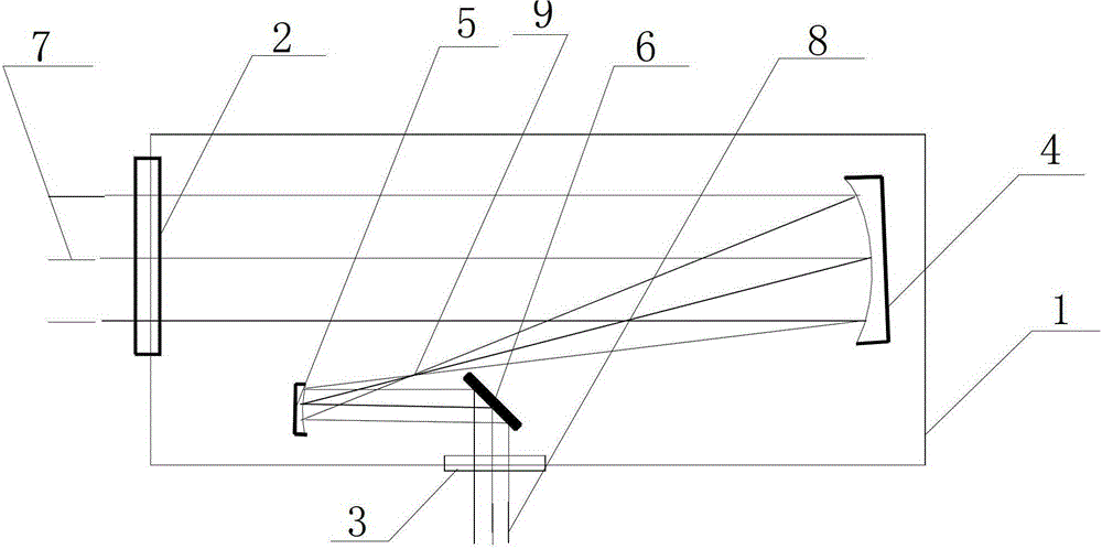
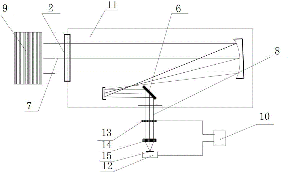
[0021] The invention provides a high-magnification beam conversion device, such as figure 1 As shown, it includes a housing 1, and the housing 1 is provided with an incident window 2 for incident light 7 and an exit window 3 for exiting light, between the entrance window 2 and the exit window 3 A parabolic primary mirror 4, a parabolic secondary mirror 5, and a plane reflector 6 are arranged in the housing 1 between them, the parabolic primary mirror 4 is arranged at a position corresponding to the incident window 2, ...


PUM


Abstract

The invention discloses a large aperture laser far field distribution detection system based on beam transformation and a method thereof. The system comprises a shell which is provided with an incident window for introducing light and an emitting window for emitting light out. A paraboloid primary lens, a paraboloid secondary lens and a plane reflection lens are arranged between the incident window and the emitting window in the shell. The paraboloid primary lens is arranged at a position corresponding to the incident window, and the paraboloid secondary lens is arranged under the incident window and is corresponding to the plane reflection lens. Through using a reflection high magnification beam conversion device, the conversion of a wide band, large field of view, and high magnification light beam apertures is realized, combined with Fourier transform lens with different focal lengths, the high precision testing requirements of laser far-field distribution of different apertures and different bands of a space optical communication terminal machine are satisfied, the conversion measurement of a light beam from near field distribution to far field distribution is realized, and the detection accuracy of the light beam far field distribution is improved.

Description

technical field [0001] The invention relates to the technical field of space optical communication testing, in particular to a large-aperture laser far-field distribution detection system and method based on beam conversion. Background technique [0002] Space optical communication uses laser as an information carrier to transmit high-speed data in space. It is an important research direction in the field of modern large-capacity space communication. It has large capacity, high speed, small size, light weight, low power consumption, and reliability. High, confidentiality and security are good, so it has broad military and civilian prospects. In the past 20 years, developed countries in the world have carried out extensive research on various forms of optical communication systems such as satellite-orbit, satellite-ground, and space-ground systems. my country's space optical communication technology has also made great progress. [0003] In the development process of the spa...

Claims


Application Information

Patent Timeline
Patent Type & Authority Patents(China)
IPC IPC(8): G02B17/06H04B10/07
Inventor 孙权社赵发财陈坤峰王少水王国权郑祥亮
Owner THE 41ST INST OF CHINA ELECTRONICS TECH GRP
Learn More