
Liquid crystal panel, display device, manufacturing and driving method thereof

A technology of liquid crystal panel and liquid crystal layer, which is applied in static indicators, optics, instruments, etc., can solve problems such as affecting the optical display characteristics of products, uneven transmittance of display panels, and poor distribution.

Inactive Publication Date: 2016-01-06
BEIJING BOE OPTOELECTRONCIS TECH CO LTD
View PDF8 Cites 0 Cited by
  • Summary
  • Abstract
  • Description
  • Claims
  • Application Information

AI Technical Summary

Problems solved by technology

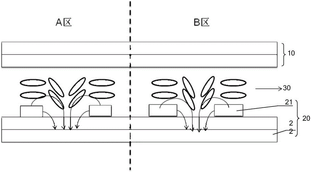
[0004] The inventors found that the prior art has at least the following problems: During the production process of the array substrate, on a glass substrate (finally made into an array substrate, the array substrate and the color filter substrate can be divided into multiple independent display panels after boxing) Although the characteristic parameters of each layer (such as layer thickness, line width, etc.) There is a large difference between the corner area and other areas, and the distribution is poor
One of the main manifestations of the above-mentioned poor distribution is that on the same glass substrate, the sizes of the first electrodes 21 (strip electrodes) are difficult to be completely consistent, which will result in different display panels (corresponding to different regions of the same glass substrate) There are differences in the electric field distribution, and the circuit adjustment codes used by different display panels are consistent for economical and mass production, resulting in differences in the transmittance at the center and corner areas of the same glass substrate, reflected in the product The above shows that different display panels have uneven changes in transmittance; on the other hand, due to the end difference in height between the second electrode and the first electrode, there is inevitably a vertical electric field between the two layers of electrodes in the liquid crystal cell. , affect the liquid crystal distribution in the edge area of ​​the pixel, the above two aspects will seriously affect the optical display characteristics of the product

Method used


Image

  • Liquid crystal panel, display device, manufacturing and driving method thereof
  • Liquid crystal panel, display device, manufacturing and driving method thereof
  • Liquid crystal panel, display device, manufacturing and driving method thereof

Examples


Embodiment 1

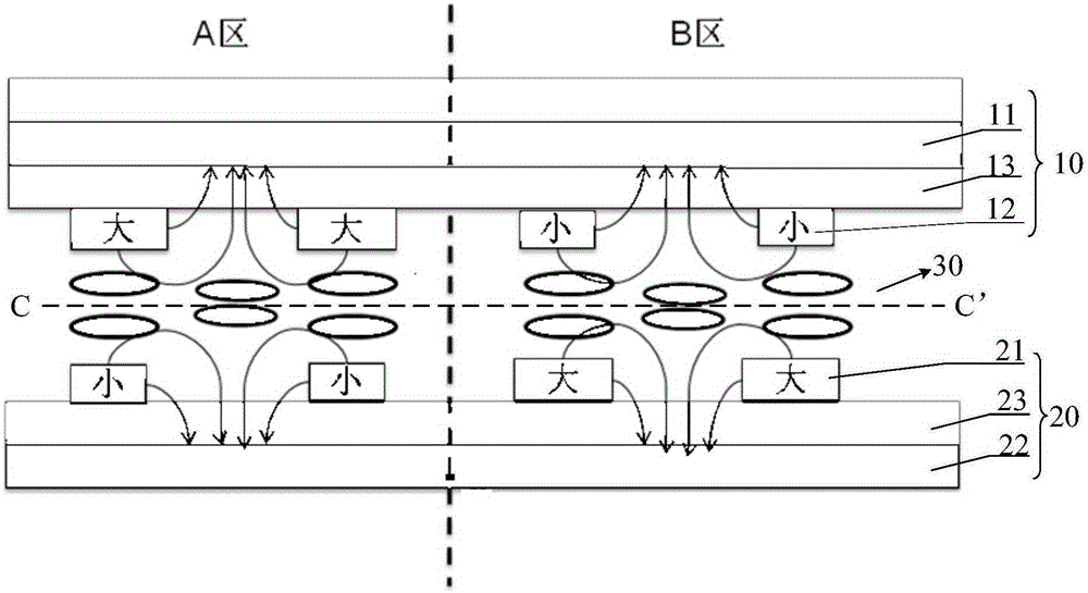
[0062] Such as figure 2 As shown, the embodiment of the present invention provides a liquid crystal panel, including an array substrate 20, a color filter substrate 10, and a liquid crystal layer 30 disposed between the two substrates. The array substrate 20 is provided with a first electrode 21 and a second electrode in different layers. 22. The third electrode 12 and the fourth electrode 11 are arranged in different layers on the color filter substrate 10, the first electrode 21 and the third electrode 12 are arranged opposite to each other, the first electrode 21 and the third electrode 12 are slit-shaped electrodes, and the second The electrode 22 and the fourth electrode 11 are plate-shaped electrodes, and the first electrode 21 and the third electrode 12 are respectively located on the side of the second electrode 22 and the fourth electrode 11 close to the liquid crystal layer 30 .

[0063] After the color filter substrate 10 and the array substrate 20 are aligned, the...

Embodiment 2

[0078] An embodiment of the present invention provides a liquid crystal panel, which is different from Embodiment 1 in that, refer to figure 2 As shown, a passivation layer 23 is provided between the first electrode 21 and the second electrode 22 on the array substrate 20, and a second passivation layer is provided between the third electrode 12 and the fourth electrode 11 on the color filter substrate 10. layer 13; and, the second passivation layer 13 on the color filter substrate 10 and the second passivation layer 23 on the array substrate have the same material and manufacturing process parameters, and are processed by the same equipment, so that the second The second passivation layer 13 has the same trend as the poor distribution of the passivation layer 23 (mainly the change of the thickness of the passivation layer). After the box is aligned, the distribution of the second passivation layer 13 and the passivation layer 23 is opposite (Refer to Embodiment 1 and image...

Embodiment 3

[0080] An embodiment of the present invention provides a liquid crystal panel, which is different from Embodiment 1 in that, refer to figure 2 As shown, the fourth electrode 11 and the second electrode 22 of the array substrate 20 have the same material and manufacturing process parameters, and are processed by the same equipment, so that the prepared fourth electrode 11 has the same characteristics as the second electrode 22. Consistent distribution of bad trends, after pairing boxes such as figure 2 As shown, making the poor distribution trend of the fourth electrode 11 and the second electrode 22 is opposite, can compensate the difference in electric field distribution caused by the poor distribution of the process parameters of the first electrode 21 and the second electrode 22, and improve the display effect of the product.


PUM


Abstract

A liquid crystal panel, a display device, and a manufacturing method and a driving method thereof are provided. The liquid crystal panel comprises an array substrate (20), a color filter substrate (10), and a liquid crystal layer (30) disposed between two substrates; the array substrate (20) is provided with a first electrode (21) and a second electrode (22) thereon in different layers, the color filter substrate (10) is provided with a third electrode (12) and a fourth electrode (11) thereon in different layers, the first electrode (21) and the third electrode (22) are disposed opposite to each other, the first electrode (21) and the third electrode (12) are slit-like electrodes, the second electrode (22) and the fourth electrode (11) are plate-like electrodes, the first electrode (21) and the third electrode (12) are respectively located on sides close to the liquid crystal layer of the second electrode (22) and the fourth electrode (11). The driving method of a display device comprises: with regard to each frame of image, calculating and acquiring an average value of pixel voltages applied to pixel electrodes when the frame of image is shown, and applying the average value to the third electrode (12) or the fourth electrode (11) of the color filter substrate (10); or, in any one pixel region, the third electrode (12) is applied with a same signal as the first electrode (11), and the fourth electrode (11) is applied with a same signal as the second electrode (22).

Description

technical field [0001] The invention relates to the display field, in particular to a liquid crystal panel, a display device and a manufacturing and driving method thereof. Background technique [0002] The planar field mode refers to the parallel electric field that mainly drives the rotation orientation of the liquid crystal, including the in-plane switching mode (In-Plane Switching, referred to as: IPS) and the advanced super-dimensional field switching mode (Advanced-SuperDimensional Switching, referred to as: ADS). The ADS mode forms a multi-dimensional electric field through the parallel electric field generated by the edge of the pixel electrode or the common electrode in the same plane and the longitudinal electric field generated between the pixel electrode and the common electrode, so that the liquid crystal molecules in the liquid crystal cell can be rotated and converted, thereby improving the plane alignment system. Improve the working efficiency of liquid cryst...

Claims


Application Information

Patent Timeline
Patent Type & Authority Patents(China)
IPC IPC(8): G02F1/1343G02F1/1333G02F1/133H01L27/12
CPCG02F1/134363G09G3/3648G09G2300/0434G09G2360/16G02F1/134372G02F1/133514G02F1/133516G02F1/13439G02F1/136204G02F1/136286G02F1/1368G09G3/3696G09G2300/0426G02F1/136295
Inventor 吴昊
Owner BEIJING BOE OPTOELECTRONCIS TECH CO LTD
Learn More