
Integrated type miniaturized round proximity switch

A proximity switch and integrated technology, which is applied in the field of miniaturized circular proximity switches, can solve problems such as the influence of measurement accuracy, the unsatisfactory structure of the separation of the sensor and the conversion circuit, and the easy interference of the inductance signal, so as to reduce the weight of the product and improve the quality of the product. The effect of product testing accuracy and simple structure

Inactive Publication Date: 2013-11-27
CHENGDU KAITIAN ELECTRONICS
View PDF4 Cites 9 Cited by
  • Summary
  • Abstract
  • Description
  • Claims
  • Application Information

AI Technical Summary

Problems solved by technology

Due to the size of the signal conversion box and its resistance to environmental conditions, it is far away from the sensor. Therefore, the signal transmission cable is considered to be (15~20) m. Since the inductive signal is easily interfered, although shielding is adopted, it has a significant impact on the measurement accuracy.
At the same time, it can be found that if the carrier body does not require more measuring points, the structure in which the sensor is separated from the conversion circuit is not ideal.

Method used


Image

  • Integrated type miniaturized round proximity switch
  • Integrated type miniaturized round proximity switch
  • Integrated type miniaturized round proximity switch

Examples


Embodiment Construction

[0017] The present invention will be further described below in conjunction with the accompanying drawings and embodiments, but the present invention is not limited to the scope of the described embodiments.

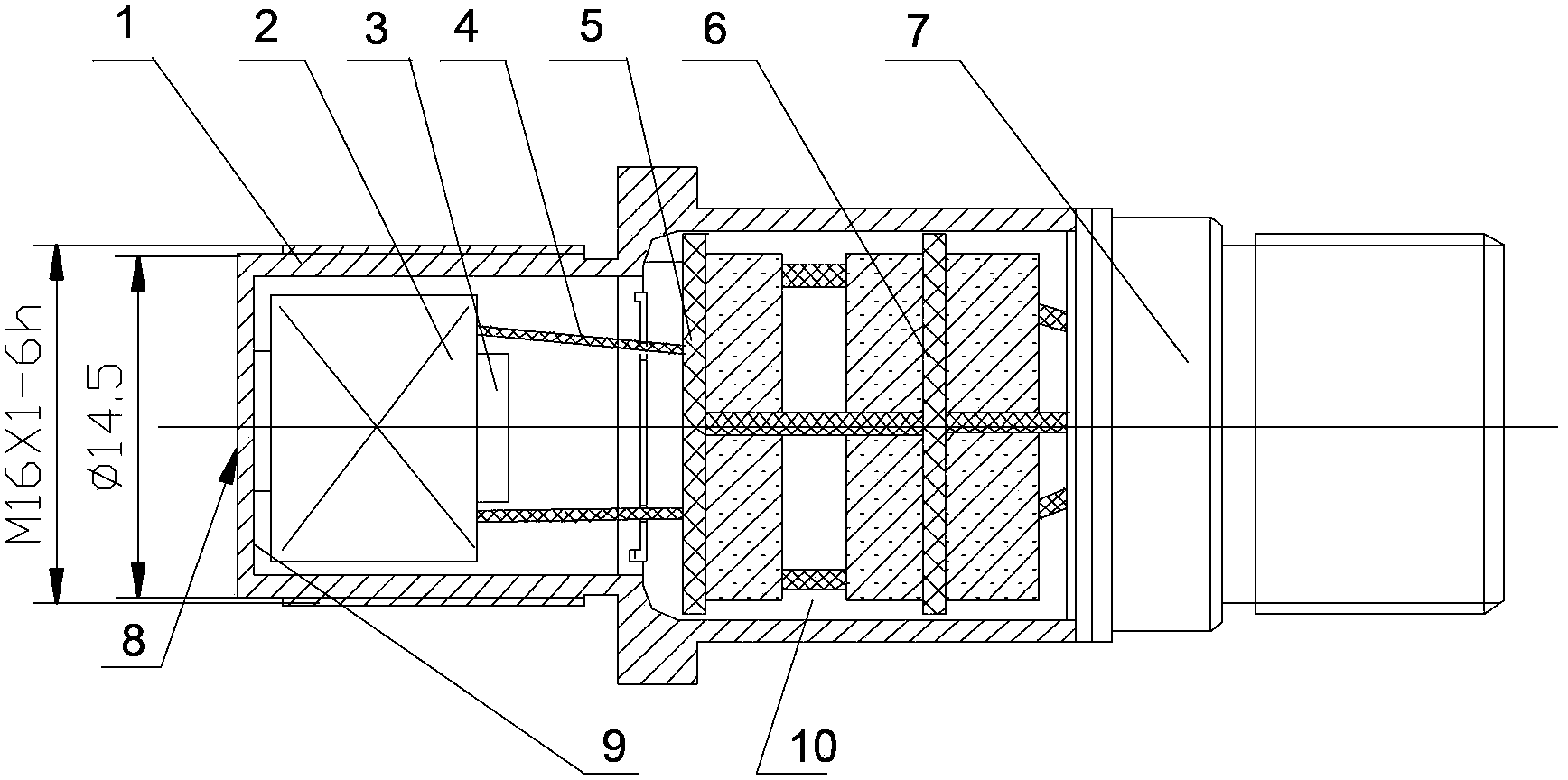
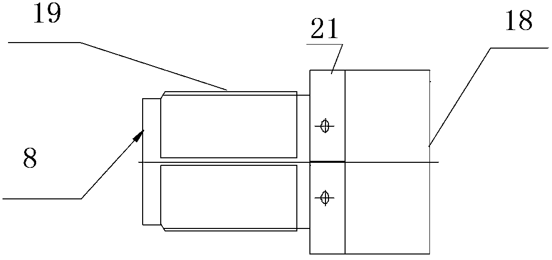
[0018] exist Figure 1 to Figure 5 In the described embodiment of the miniaturized circular proximity switch, the miniaturized circular proximity switch has a working section with an outer diameter of 14.5mm and a length of 3mm, extending to the right to the carrier mechanical interface to install the thread 19, and the end of the thread is the side length S = 21mm regular hexagonal flange. The other side of the flange is a thin-walled cylinder with a diameter of about Φ21. The metal casing opening 18 is vacuum-tightly welded to the outer surface of the corresponding part of the socket 7 . The stabilized power supply board 6 is equipped with a power supply module and required peripheral devices, and the receiving circuit board 5 is equipped with a micro-inductance rece...


PUM

PropertyMeasurementUnit
Outer diameteraaaaaaaaaa
Lengthaaaaaaaaaa

Abstract

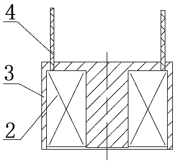
The invention provides an integrated type miniaturized round proximity switch. The integrated type miniaturized round proximity switch comprises a metal outer shell (1), a minitype inductive transducer, a switching circuit board, a socket (7), a micro inductive type approach transducer and switching circuit components, wherein the maximum outer diameter of the metal outer shell (1) is smaller than 23mm, the minitype inductive transducer is arranged in the metal outer shell (1) and is provided with a coil assembly (3), and the socket (7) is fixedly connected at the tail end of the metal outer shell. The micro inductive type approach transducer is formed by an inductive coil assembly (2) and an iron core, the opening end of the iron core is tightly attached to the inner bottom (9) of the metal outer shell of an inductive head, the inductive coil assembly is electrically connected with a switching circuit through two coil lead wires (4), the switching circuit components are composed of a receiving circuit board (5) and a voltage-stabilized source board (6), the switching circuit components are regarded at a unified independent body and are pasted and solidified in a rear cavity (10) of the metal outer shell through insulation glue. According to the integrated type miniaturized round proximity switch, the independent inductive transducer, an independent electronic component and an independent power source component are regarded as the unified independent body, the size is smaller than that of an independent miniaturized proximity switch in the prior art, and the size and the weight of a control box are reduced for a carrier.

Description

technical field [0001] The invention relates to a miniaturized circular proximity switch mainly used for measuring the proximity distance between a moving object and a target ≤ 2.15mm and outputting a discrete signal. Background technique [0002] The so-called proximity switch means that the measured target does not need to touch the switch body, but only needs to approach within the specified distance, and the switch will send out the specified signal; on the contrary, when the measured target leaves the specified distance, the switch will send out another specified signal. kind of signal. A proximity switch is a product that senses the proximity of an object and outputs a discrete signal. It uses the sensitivity of the built-in proximity sensor to the approaching ferromagnetic object to measure the inductance value of the measured object near a specific point, and transmits this characteristic to the receiving chip. The condition of the dot position is indicated by the ...

Claims


Application Information

Patent Timeline
IPC IPC(8): H03K17/95
Inventor 薛正国
Owner CHENGDU KAITIAN ELECTRONICS
Learn More