
Adaptive beamforming method based on convex combination

An adaptive beam and adaptive filter technology, applied in the direction of space transmit diversity, diversity/multi-antenna system, etc., can solve problems such as large steady-state error

Inactive Publication Date: 2013-11-27
SOUTHWEST JIAOTONG UNIV
View PDF2 Cites 22 Cited by
  • Summary
  • Abstract
  • Description
  • Claims
  • Application Information

AI Technical Summary

Problems solved by technology

This algorithm has a faster convergence speed and better stability, but the steady-state error is still large

Method used


Image

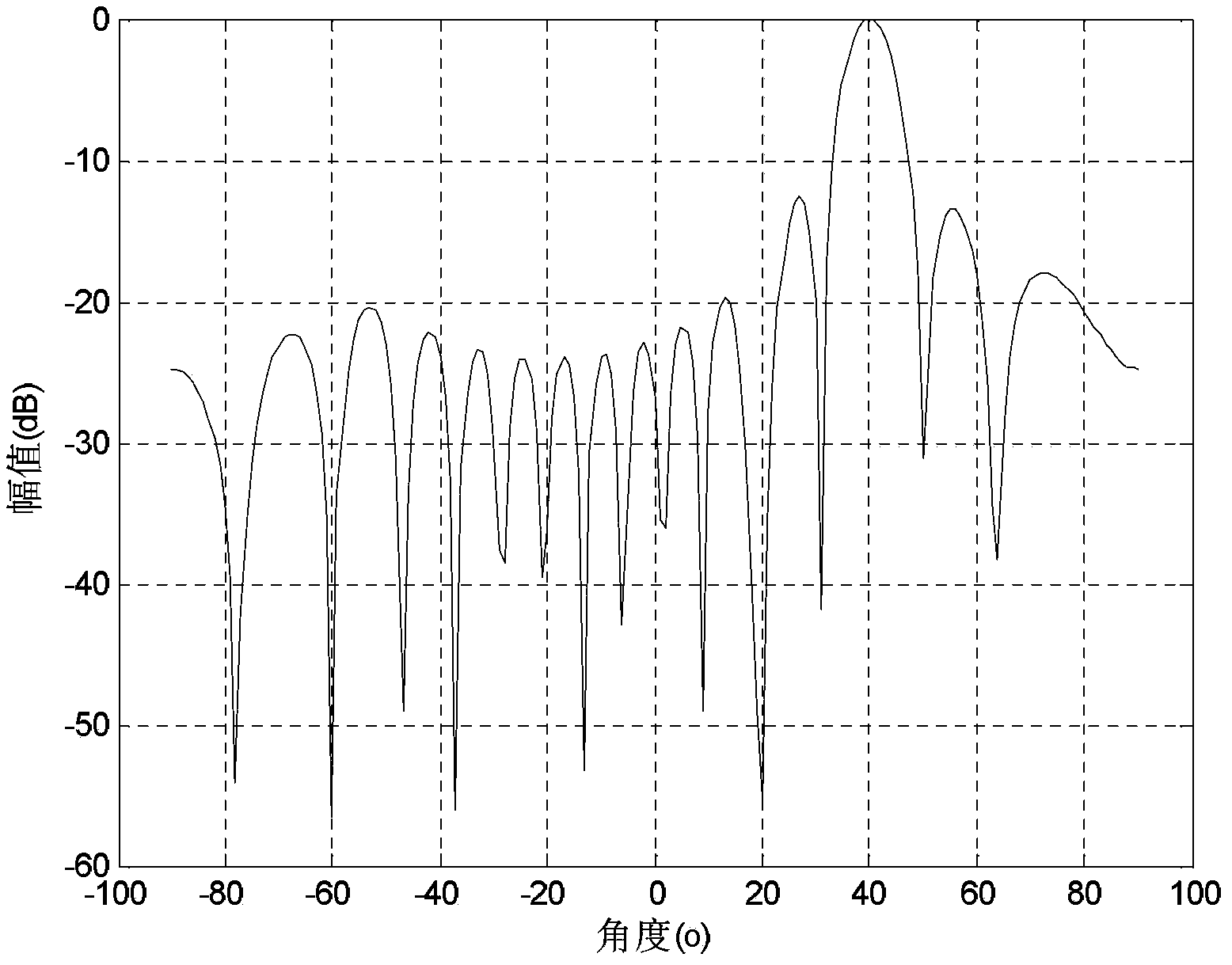
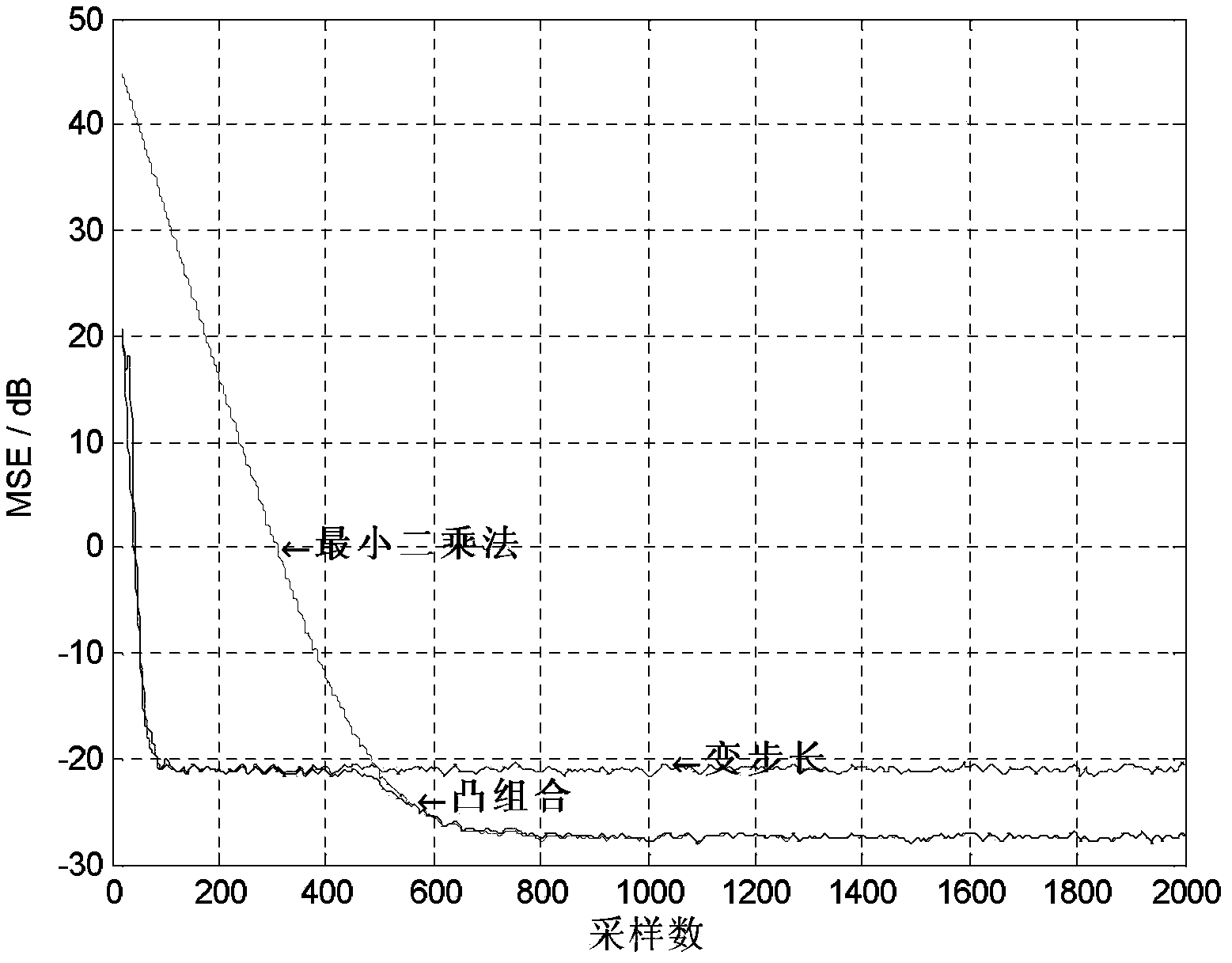
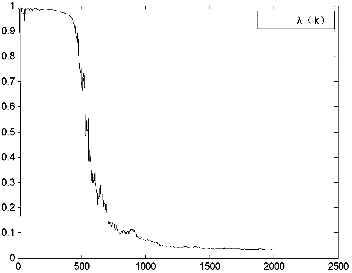
  • Adaptive beamforming method based on convex combination
  • Adaptive beamforming method based on convex combination
  • Adaptive beamforming method based on convex combination

Examples


Embodiment

[0056] A method of adaptive beamforming based on convex combination, comprising the following steps:

[0057] A. Reception and discrete processing of communication signals

[0058] A uniform line array antenna composed of 16 antennas is selected to receive communication signals, and the distance between adjacent antennas in the array is 1 / 2 of the wavelength of the communication signal; the communication signal received by the antenna is discretized to obtain a discrete communication signal matrix X(k), The communication signal matrix X(k) includes the desired signal and interference signal S(k) and Gaussian white noise N(k), namely:

[0059] X(k)=AS(k)+N(k);

[0060] Among them, k is the sampling time point,

[0061] S(k) is the vector expression of the communication signal matrix X(k), S(k)=[s 1 (k)s 2 (k) ... s i (k)] T ,s i (k) is the sub-signal of the i-th signal source of the communication signal matrix X(k) in the space domain,

[0062] A is the antenna array fl...


PUM


Abstract

The invention discloses an adaptive beamforming method based on a convex combination. The method mainly comprises the following steps: an array antenna receives a signal, a least square adaptive filter and a variable step size adaptive filter are constructed, the weight updating formulas of two adaptive filters are subjected to convex combination to obtain the weight of a combined filter, the received signal is inputted to obtain a best weight vector through a convex combination filter, and the best weight vector and a scanning vector are subjected to multiplying to obtain an output signal of the antenna. The method has the advantages of fast convergence speed and small steady-state error, and the mobile communication has the advantages of high signal to noise ratio and good stability.

Description

technical field [0001] The invention belongs to an adaptive beam forming method in a mobile communication system. Background technique [0002] In recent years, with the rapid development of mobile communication system technology, smart antennas have become a hot spot in mobile communication. Smart antenna technology has been extended from the time domain, frequency domain, and code domain to the space domain, increasing the capacity of the system as much as possible on very limited spectrum resources. The smart technology of smart antennas in the space domain is to use the adaptive beamforming algorithm to generate the corresponding weights of the sub-signals (each antenna) in the antenna array signal, through the weight gain, the quasi-desired signal is enhanced in the signal output, and through the attenuation of the weight The interference signal is suppressed, thereby improving the signal-to-noise ratio of the antenna output. [0003] The core of smart antenna beamfor...

Claims


Application Information

Patent Timeline
Patent Type & Authority Applications(China)
IPC IPC(8): H04B7/04H04B7/06H04B7/08
Inventor 赵海全杨磊
Owner SOUTHWEST JIAOTONG UNIV
Learn More