Morse signal self-adaptive recognition method based on backtracking
A recognition method and backtracking method technology, applied in the field of Morse signal recognition, can solve the problems of dot-dash value change, poor self-adaptive ability, change, etc., to reduce the intermediate process, strong self-adaptive ability, code word recognition rate high effect
- Summary
- Abstract
- Description
- Claims
- Application Information
AI Technical Summary
Problems solved by technology
Method used
Image
Examples
Embodiment 1
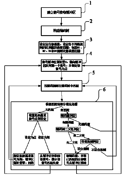
[0041] Such as figure 1 As shown, the main process of the Morse signal adaptive identification method based on the backtracking method of the present invention is:
[0042]Step 1. Establish a Morse signal receiving buffer: First, a Morse signal receiving buffer must be established in the memory (RAM) to store the received Morse signal. out principle.
[0043] The signal receiving buffer is established to match the speed inconsistency between the signal sending by the signal sending device and the signal decoding by the signal receiving device. The signal receiving buffer is a queue, which conforms to the first-in-first-out principle of the queue. This method establishes a signal buffer pointer in the signal receiving buffer to indicate the signal to be fetched during the execution of the method. The buffer pointer starts counting from 0, that is, 0 points to the first signal of the queue. In this method, fetching the next signal is realized by moving the buffer pointer. ...
Embodiment 2
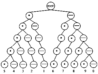
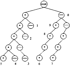
[0066] In practical application, the signal receiver and the sender agree on a short code, and set the ratio error range between dots and dots, strokes and strokes to be between 0.7 and 1.5, and the ratio error range between strokes and dots to be between 2.2 and 4.5. When the receiving buffer receives the signal string, the square wave quantization value is "201 -112 49 -310 55". Take out m first 1 "201" and assume that the signal is a point, corresponding to the left node (the first node) of the second layer in the short code tree, take the next signal m 2 "49", its ratio is 4.1, beyond the point-to-point ratio error range, the matching fails, backtracking. Assume again that m 1 "201" is a stroke, corresponding to m 1 The right child node (the second node in the second layer in the short code tree), which is related to m 2 The ratio of "49" is 4.1, which is in line with the scale range of dots, m 2 is a point, corresponding to m 1 The left child node of (the third node...
Embodiment 3
[0068] In practical application, the signal receiver and the sender agree on a short code, and set the ratio error range between dots and dots, strokes and strokes to be between 0.7 and 1.5, and the ratio error range between strokes and dots to be between 2.2 and 4.5. When the receiving buffer receives the square wave quantization value of the signal string is "58 -65 175 -210 60". Take out m first 1 "58" and assume that the signal is a point, corresponding to the left node (the first node) of the second layer in the short code tree, take the next signal m 2 "175", its absolute value ratio is 0.33, in line with the dot-dash ratio, m 2 "175" is a stroke, corresponding to m 1 Right child node (2nd node of layer 2). This node already has a stored value of "1", has no child nodes, and the encoded value of the signal string is "1". "58 -65 175 -210" will be removed from the buffer, and the pointer will return to 0, pointing to "60".
PUM
 Abstract
Description
Claims
Application Information
 - R&D
- Intellectual Property
- Life Sciences
- Materials
- Tech Scout
- Unparalleled Data Quality
- Higher Quality Content
- 60% Fewer Hallucinations
Browse by: Latest US Patents, China's latest patents, Technical Efficacy Thesaurus, Application Domain, Technology Topic, Popular Technical Reports.
© 2025 PatSnap. All rights reserved.Legal|Privacy policy|Modern Slavery Act Transparency Statement|Sitemap|About US| Contact US: help@patsnap.com


