Temperature averaging device of steam chamber heat pipe/microchannel cold plate composite structure

A composite structure and micro-channel technology, applied in the direction of cooling/ventilation/heating transformation, etc., can solve the problems of obvious size limitation, failure to achieve overall temperature uniformity, and difficulty in achieving uniform temperature effect, etc., to achieve thin height, high utilization rate, The effect of improving the utilization rate

Active Publication Date: 2013-11-27
NANJING UNIV OF SCI & TECH
View PDF3 Cites 12 Cited by
  • Summary
  • Abstract
  • Description
  • Claims
  • Application Information

AI Technical Summary

Problems solved by technology

The microchannel cold plate has high cooling efficiency, but there are also the following problems: 1. The size limitation is obvious
The size of the micro-channel cold plate should not be too large, especially the length between the inlet and outlet should not be too long, otherwise the temperature difference of the electronic devices arranged on the surface of the micro-channel cold plate will be too large, and the required overall temperature uniformity cannot be achieved
2. The micro-channel cold plate mainly takes away the heat by forced convection, which is only applicable to heat flux density less than 100W / cm 2 Case
Under high heat flux conditions, due to the large temperature difference between the inlet and outlet of the microchannel cold plate, the temperature of the electronic devices arranged near the outlet is significantly higher than that of the electronic devices arranged near the inlet. Especially in the case of electronic devices, it is especially difficult to control the root mean square temperature difference of multiple electronic devices within an ideal range, such as 5°C, and it is difficult to achieve a good temperature uniformity effect

Method used


Image

  • Temperature averaging device of steam chamber heat pipe/microchannel cold plate composite structure
  • Temperature averaging device of steam chamber heat pipe/microchannel cold plate composite structure
  • Temperature averaging device of steam chamber heat pipe/microchannel cold plate composite structure

Examples


Embodiment Construction

[0010] Specific embodiments of the present invention will be described below in conjunction with the accompanying drawings.

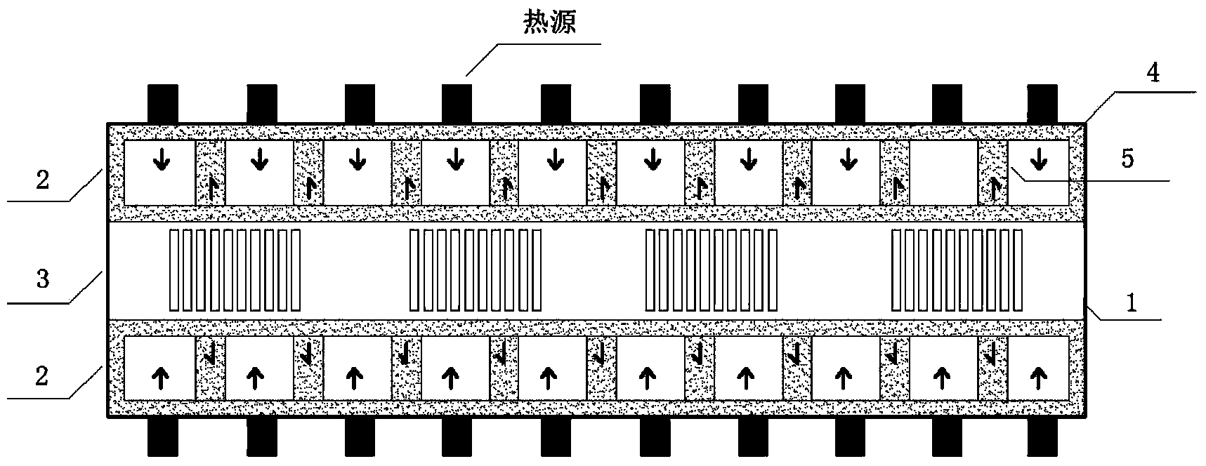
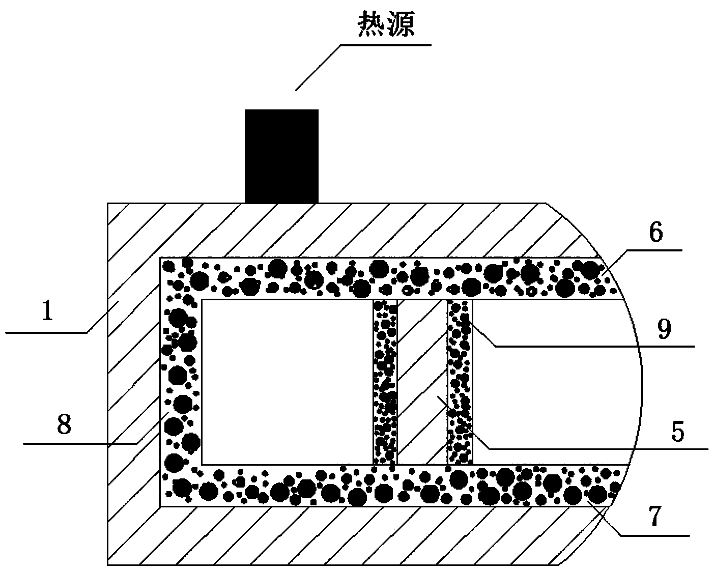
[0011] combine figure 1 , the high heat flux electronic devices arranged on the surface of the steam chamber heat pipe layer 2 ( figure 1 is referred to as the heat source) through heat conduction to transfer a large amount of heat to the capillary layer 6 on the evaporation surface of the heat pipe layer 2 in the steam chamber. Since the heat pipe layer 2 in the steam chamber is in a state of vapor-liquid two-phase saturation, the liquid working medium that absorbs heat vaporizes rapidly, accompanied by As the pressure increases, the gas working medium moves toward the capillary layer 7 on the condensation surface. When it reaches the capillary layer 7 on the condensation surface, it is cooled by the cold plate layer 3 in the middle microchannel, and the gas working medium releases the latent heat of vaporization and turns into a liquid again. Driven ...


PUM


Abstract

The invention discloses a temperature averaging device of a steam chamber heat pipe / microchannel cold plate composite structure. The device comprises a metal shell, steam cavity heat pipe layers and a microchannel cold plate layer, wherein the microchannel cold plate layer is located between the two steam cavity heat pipe layers, and the steam cavity heat pipe layers and the microchannel cold plate layer are all located in the metal shell. The liquid working medium phase-change heat exchange method is adopted for the device to transmit a large amount of heat in a gasified latent heat mode, and therefore the heat exchange capacity is remarkably improved. Because only one face of an existing steam cavity heat pipe is an evaporating face and is small in area, the utilization area of the whole is limited. The upper face and the lower face of the temperature averaging device of the composite structure are both evaporating faces, therefore, electronic components with high heating flux can be distributed on both the whole surface of the upper face and the whole surface of the lower face, the utilization rate is obviously improved, and the temperature averaging device of the composite structure can meet the thermal control requirements of the electronic components with high heating flux in the electronic industry field better. The temperature averaging device of the steam chamber heat pipe / microchannel cold plate composite structure is smaller in height, the height of a single microchannel cold plate layer in the prior art is 9mm, but the overall height of the temperature averaging device of the steam chamber heat pipe / microchannel cold plate composite structure is not larger than 9 mm.

Description

technical field [0001] The invention relates to the field of heat dissipation of electronic devices, in particular to a temperature equalization device with a steam chamber heat pipe / microchannel cold plate composite structure, which is used for uniform temperature heat dissipation of high heat flux density electronic devices. technical background [0002] In the field of electronics industry, the current heat flux density of electronic devices has exceeded 100W / cm 2 . Every time the temperature of electronic devices rises by ten degrees Celsius, the reliability will decrease by 50%, so temperature control of high heat flux electronic devices is an extremely urgent need. Common heat dissipation methods include air cooling, liquid cooling and phase change cooling. Document 1 (Research on liquid-cooled cold plates, Xu Dehao, Yang Dongmei, Electromechanical Engineering, Issue 1, 2006, pages 4-6) pointed out that when the heat flux density is greater than 5W / cm 2 At this time...

Claims


Application Information

Patent Timeline
Patent Type & Authority Applications(China)
IPC IPC(8): H05K7/20
Inventor 李强宣益民郭磊
Owner NANJING UNIV OF SCI & TECH
Why Eureka
Try Eureka