Pipe cutting device

A pipe cutting device and hose technology, which is applied in metal processing and other directions, can solve the problems of high manufacturing cost, large floor space, complex structure, etc., and achieve the effects of low processing and manufacturing cost, safe and reliable use, and improved production efficiency

Active Publication Date: 2013-12-04
NINGBO SOOJEE SANITARY WARE
View PDF5 Cites 2 Cited by
  • Summary
  • Abstract
  • Description
  • Claims
  • Application Information

AI Technical Summary

Problems solved by technology

The fully automatic pipe cutting device with automatic feeding, such as the pipe cutting device disclosed in the Chinese patent whose application number is 201120096153.2 and whose name is "a workbench of a fully automatic pipe cutting machine", has complex structure and high manufacturing cost, accounting for Problems such as large land area, high energy consumption and maint

Method used


Image

  • Pipe cutting device
  • Pipe cutting device

Examples


Embodiment Construction

[0018] The technical solutions of the present invention will be further specifically described below through the embodiments and in conjunction with the accompanying drawings.

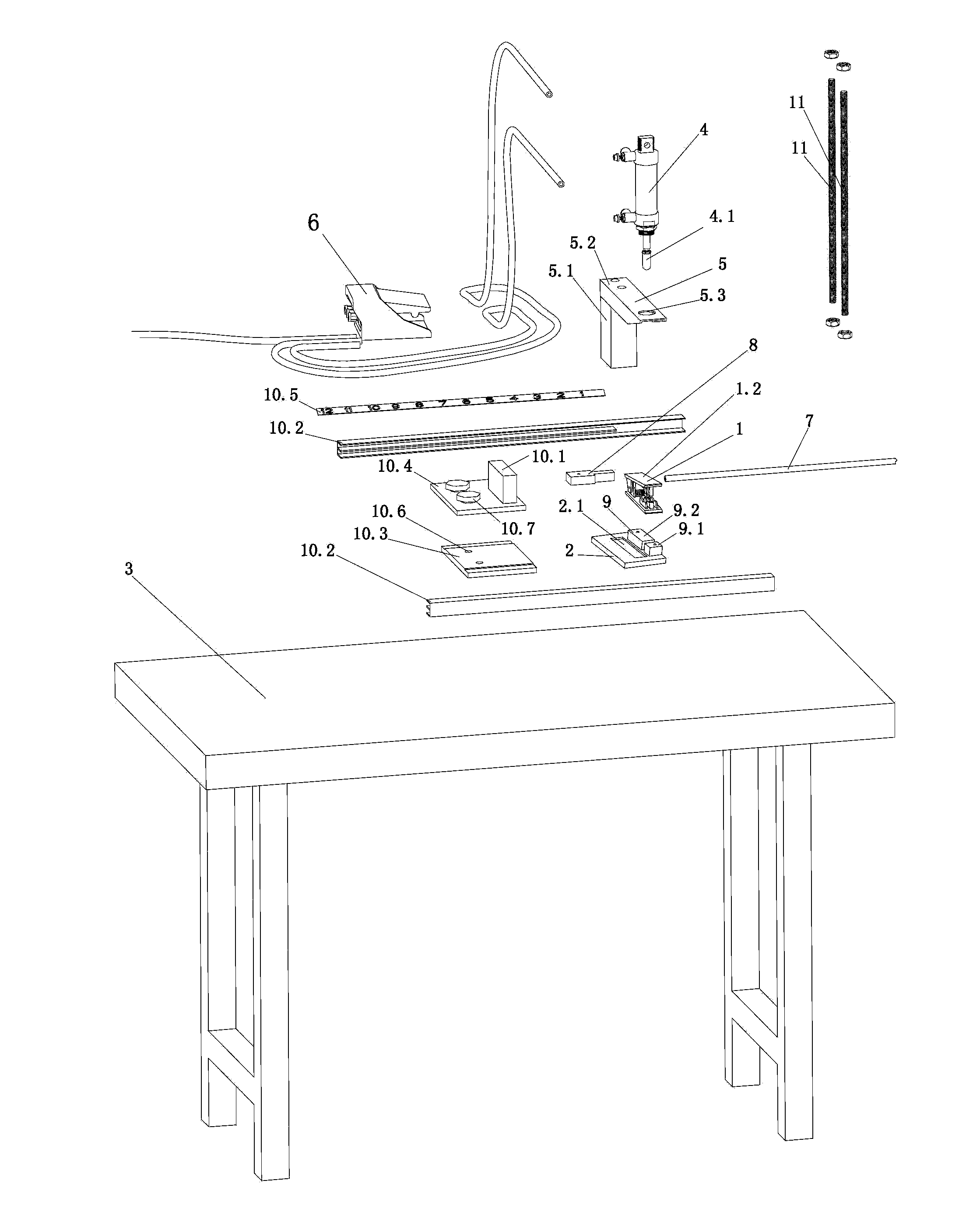
[0019] Such as figure 1 As shown, the present invention includes a cutter assembly 1, a cutter assembly mounting plate 2, a working platform 3, a cylinder 4, a cylinder frame 5, a foot switch 6, a fixed pressure block 8, an enhanced safety assembly 9 and a size control device. The working platform 3 is provided with some mounting screw holes or mounting through holes not shown in the figure. The tool assembly mounting plate 2 is a rectangular plate, which is fixed on the working platform 3 with bolts not shown in the figure; the pedal switch is connected to the cylinder 4 and the gas source not shown in the figure through the corresponding communicating air pipe;

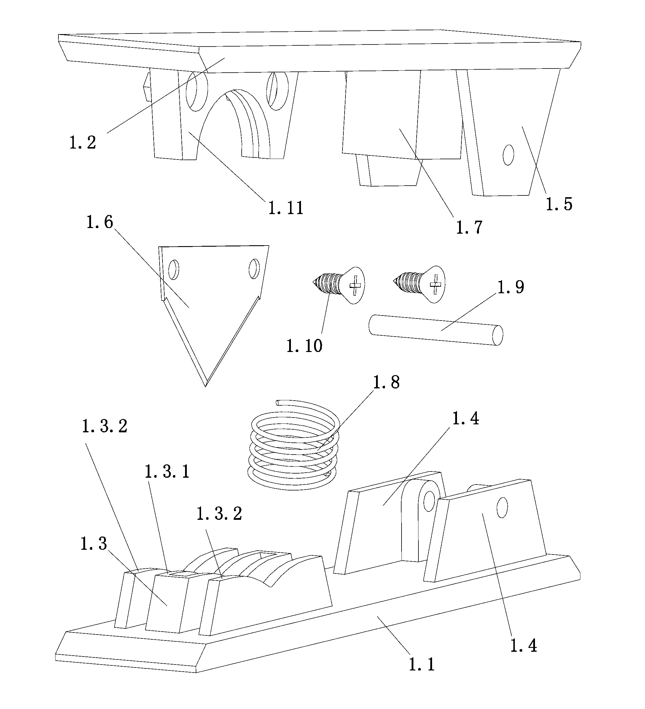
[0020] Such as figure 2 As shown, the cutter assembly 1 includes a fixed base plate 1.1, a cutter fixed plate 1.2 and a cutter fixed pla...


PUM


Abstract

A pipe cutting device comprises a cutter assembly, an installation plate of the cutter assembly, a working platform, an air cylinder, an air cylinder frame, a foot switch, a fixed pressing block, an enhanced safety component and a size control device; the cutter assembly comprises a fixed bottom plate, a cutting knife fixing plate and a cutting knife fixing plate return spring; a hose supporting base group and a cutting knife fixing plate connecting base are fixedly arranged at front and back ends of the fixed bottom plate respectively, and the hose supporting base group comprises a main supporting base and a protective supporting base; the rear end of the cutting knife fixing plate is hinged to the cutting knife fixing plate connecting base; a piston head of the air cylinder abuts against the cutting knife fixing plate; the size control device comprises a size control stopping block; the fixed bottom plate is placed inside a positioning hole formed in the installation plate of the cutter assembly and is pressed against and fixed on the working platform through the fixed pressing block; the enhanced safety component is fixedly arranged on the right side of the hose supporting base group and comprises front and back enhanced safety blocks, highest points of the front and back enhanced safety blocks are higher than the highest position of a tip of a cutting knife, and the distance between the front and back enhanced safety blocks is 10-20mm larger than the diameter of a hose.

Description

[0001] technical field [0002] The invention relates to hose processing equipment for sanitary ware, in particular to a pipe cutting device. [0003] Background technique [0004] In the field of sanitary ware production, it is often necessary to use a pipe cutting device to cut long rolls of raw material hoses into sections of short pipes for use. Existing pipe cutting device mainly contains two kinds of manual feeding pipe cutting device and automatic feeding automatic pipe cutting device. The fully automatic pipe cutting device with automatic feeding, such as the pipe cutting device disclosed in the Chinese patent whose application number is 201120096153.2 and whose name is "a workbench of a fully automatic pipe cutting machine", has complex structure and high manufacturing cost, accounting for Large area, high energy consumption and high maintenance costs. The existing pipe cutting device with manual feeding usually requires the cooperation of two workers to complete...

Claims


Application Information

Patent Timeline
IPC IPC(8): B26D7/28B26D7/22
Inventor 马忠会沈岳军
Owner NINGBO SOOJEE SANITARY WARE
Why Eureka
Try Eureka