Hydraulic generating set for deceleration strip

A power generation device and deceleration belt technology, which is applied in the direction of machines/engines, mechanical equipment, mechanisms that generate mechanical power, etc., can solve the problems of high mechanical friction, difficult repair, short life, etc., to slow down the instantaneous impact and reduce energy loss , the effect of prolonged action time

Inactive Publication Date: 2013-12-04
HARBIN ENG UNIV
View PDF6 Cites 13 Cited by
  • Summary
  • Abstract
  • Description
  • Claims
  • Application Information

AI Technical Summary

Problems solved by technology

[0004] (1) The gear structure is too complex, including a huge mechanical power transmission device to drive the flywheel, and then drive the generator to generate electricity through the flywheel, and finally collect and store the energy. There are too many intermediate energy transmission links, more mechanical wear, and low power generation efficiency
[0005] (2) Due to the compressibility of gas, the mechanical transmission of the pneumatic power generation device is unstable, and the sealing performance of the device is high, which will cause large friction and serious energy loss during mechanical movement
[0006] (3) The current hydraulic power generation device wastes a lot of hydraulic energy in the cycle process, and the energy recovery efficiency is low
[0007] (4) The equipment is integrated, it is not easy to repair after damage, it is easily affected by the harsh environment of the road, and its life is short so it cannot be popularized
[0008] (5) The equipment cost and maintenance cost are too high, and the gain outweighs the gain

Method used


Image

  • Hydraulic generating set for deceleration strip
  • Hydraulic generating set for deceleration strip

Examples


Embodiment Construction

[0019] The present invention is described in more detail below in conjunction with accompanying drawing example:

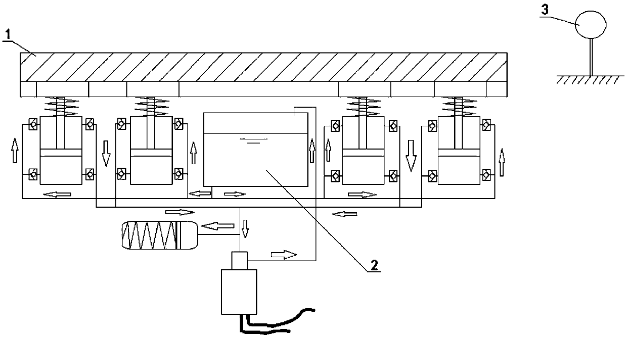
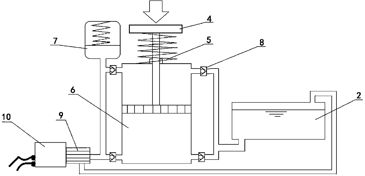
[0020] combine Figure 1~2 , the speed bump 1 of the present invention, the generator 10 and the fuel tank 2 are fixedly connected with a number of positioning round blocks 4 under the speed bump 1, and each positioning round block 4 is connected with a piston rod, and the piston rod is connected with the double-acting hydraulic cylinder 6 The pistons inside are connected, and a return spring 5 is arranged between the positioning round block 4 and the double-acting hydraulic cylinder 6; the double-acting hydraulic cylinder 6 is respectively connected with the hydraulic motor 9 and the oil tank 2 through the confluence pipeline, and the hydraulic motor 9 is connected with the generator 10, the oil return port of the hydraulic motor 9 is connected to the oil tank 2; a check valve 8 is provided at the junction of the confluence pipeline and the double-acting hydrauli...


PUM


Abstract

The invention aims to provide a hydraulic generating set for a deceleration strip. The hydraulic generating set comprises the deceleration strip and a generator, wherein the generator, an oil tank and generation units are arranged below the deceleration strip; each generation unit comprises a positioning circular block; the upper side of each positioning circular block is contacted with the deceleration strip; a dual-action hydraulic cylinder is arranged below each positioning circular block; each dual-action hydraulic cylinder is provided with a piston and a piston rod which are connected with each other; each piston rod is connected with the corresponding positioning circular block; a return spring is arranged between each positioning circular block and the corresponding dual-action hydraulic cylinder; each dual-action hydraulic cylinder is connected with a hydraulic motor and the oil tank through convergence pipelines respectively; the hydraulic motor is connected with the generator; the oil return port of the hydraulic motor is connected with the oil tank. According to the hydraulic generating set, liquid output by a plurality of dual-action hydraulic cylinders is converged to drive the hydraulic motor to work, so that momentary impact on cylinder bodies can be slowed down, pressure is dispersed, the acting time of a vehicle is prolonged in an impact process, and a good protection effect is achieved on the entire device; mechanical energy is converted into hydraulic energy more sufficiently, so that energy loss is reduced.

Description

technical field [0001] The invention relates to a power generating device, in particular to a device for generating power by using a deceleration belt. Background technique [0002] In order to reduce the speed of the vehicle and reduce the occurrence of traffic accidents, at present, speed bumps made of elastic materials with certain elasticity are arranged laterally on the roads at the more prosperous road sections in the city, highway intersections, before toll stations, and at the entrances and exits of parking lots. However, when the vehicle passes the speed bump, the impact on the speed bump when the vehicle is driving not only damages the speed bump and the road surface, but also causes the driver to feel extremely uncomfortable driving due to the vibration and jump of the car. If the energy recovery is carried out, not only the purpose of energy saving and emission reduction can be achieved, but also the economic benefit will be very considerable due to the low cost ...

Claims


Application Information

Patent Timeline
Patent Type & Authority Applications(China)
IPC IPC(8): F03G7/00
Inventor 路勇邵志强周晓燕张成凯邵亚洲李适刘成武
Owner HARBIN ENG UNIV
Why Eureka
Try Eureka