
A biomass semi-gasifier

A semi-gasification and biomass technology, which is used in the chemical industry, household stoves/stoves, and the manufacture of combustible gases, etc., can solve problems such as the inability of the outer flame to reach the bottom of the cooker, the unfavorable heat absorption of the cooker, and the low utilization rate of heat, so as to achieve fire Fast, energy-saving effect, good combustion effect

Active Publication Date: 2018-05-15
泰安泰山产业发展有限公司
View PDF1 Cites 0 Cited by
  • Summary
  • Abstract
  • Description
  • Claims
  • Application Information

AI Technical Summary

Problems solved by technology

However, there are still three deficiencies in this technical solution. The first is that it is difficult to start a fire, the combustion is slow, and the firepower is relatively small; Low, the outer flame cannot reach the bottom of the cooker, and the heat utilization rate is low; third, the flame produced by combustible gas combustion is wide and the firepower is dispersed, which is not conducive to the cooker to absorb heat

Method used


Image

  • A biomass semi-gasifier
  • A biomass semi-gasifier
  • A biomass semi-gasifier

Examples


Embodiment Construction

[0020] Below, the embodiments of the present invention will be further described in conjunction with the accompanying drawings.

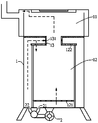
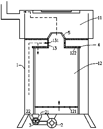
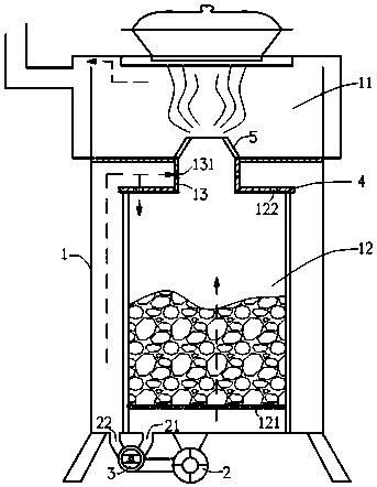
[0021] figure 1 It shows an embodiment of the first biomass semi-gasification furnace, which includes a furnace body 1, a combustion chamber 11 is arranged on the upper part of the furnace body 1, and a gasification chamber 12 is arranged on the lower part of the furnace body 1, and the gasification chamber 12 and the combustion chamber 11 are connected through a guide. The flow pipes 13 are connected; the fan 2 is connected to the main air duct 21 and the secondary air duct 22, and the main air duct 21 is connected to the main air hole 121 of the gasification chamber 12, and the main air hole 121 is located at the bottom of the gasification chamber 12; The secondary air hole 122 of the gasification chamber 12 is located at the top of the gasification chamber 12 ;

[0022] figure 2 It shows the embodiment of the second biomass semi-gasification f...


PUM


Abstract

The invention discloses a biomass semi-gasification furnace which comprises a furnace. A combustion chamber is arranged on the upper portion of the furnace, and a gasification chamber is arranged on the lower portion of the furnace and is communicated with the combustion chamber by a flow guide pipe; a fan is communicated with a main air channel and an auxiliary air channel, the main air channel is communicated with main air holes of the gasification chamber, the main air holes are positioned at the bottom or on the lower portion of the gasification chamber, the auxiliary air channel is communicated with auxiliary air holes of the gasification chamber, the auxiliary air holes are positioned on the top or the upper portion of the gasification chamber, and the auxiliary air channel is further communicated with an air mixing hole positioned on a side wall of the flow guide pipe. The biomass semi-gasification furnace has the advantages that owing to the flow guide pipe arranged between the gasification chamber and the combustion chamber, the auxiliary air holes and the air mixing hole, airflow of the auxiliary air channel can be automatically distributed at different ratios in different flow directions at an ignition stage and a combustion stage, so that the semi-gasification furnace can be ignited quickly, most of generated combustible gas is gathered at the bottom of a kitchen utensil to be combusted in a centralized manner instead of being combusted in the gasification chamber in advance owing to deficiency of oxygen, heat is released in a centralized manner, and the kitchen utensil is high in absorption and utilization rate and good in energy conservation effect.

Description

technical field [0001] The invention relates to a domestic stove using solid fuels such as firewood and coal, in particular to a biomass semi-gasifier. Background technique [0002] In the known technology, the tar generated during the working process of the biomass gasification furnace is easy to accumulate and block the gas delivery pipe and the furnace head. The combustible gas sent from the chamber is directly burned. For example, the patent document whose publication number is CN101487597 discloses a biomass semi-gasification furnace, including a panel fire cover and an inner furnace, the upper part of the inner furnace is provided with a burner, and the area surrounded by the burner is a combustion chamber , the panel fire cover is set above the inner furnace and around the burner, the outer cover of the inner furnace is provided with a secondary air cover, and the inner shell of the inner furnace and the secondary air cover form a ring-shaped secondary air cover. Th...

Claims


Application Information

Patent Timeline
Patent Type & Authority Patents(China)
IPC IPC(8): F24B1/19F24B1/183C10J3/20
CPCY02B40/00Y02P20/10
Inventor 戴松凡
Owner 泰安泰山产业发展有限公司
Learn More