
Method of Reducing Susceptibility of Square Two-frequency Laser Gyroscope

A technology of laser gyro and magnetic sensitivity, which is applied in the direction of Sagnac effect gyroscopes, measuring devices, instruments, etc., can solve the problems of cavity deformation, difficulty and error, and achieve the effect of reducing magnetic sensitivity

Active Publication Date: 2016-01-20
NAT UNIV OF DEFENSE TECH
View PDF3 Cites 1 Cited by
  • Summary
  • Abstract
  • Description
  • Claims
  • Application Information

AI Technical Summary

Problems solved by technology

However, due to the influence of many factors, this method is difficult to be free of errors. More importantly, these methods are all aimed at passive cavities. At this time, it is difficult for the resonant optical path to be exactly the same as the actual operating active cavity optical path. Consistent, and there is nothing to do about the cavity deformation caused by external factors in the future

Method used


Image

  • Method of Reducing Susceptibility of Square Two-frequency Laser Gyroscope
  • Method of Reducing Susceptibility of Square Two-frequency Laser Gyroscope
  • Method of Reducing Susceptibility of Square Two-frequency Laser Gyroscope

Examples


specific Embodiment 1

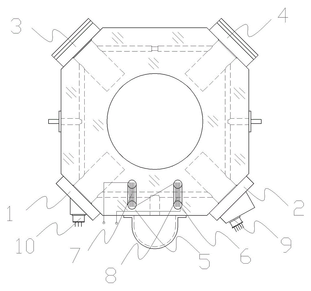
[0049] figure 1 It is a schematic diagram of a square two-frequency laser gyro with a coil installed on the gyro cavity proposed by the present invention, which includes two plane mirrors 1, 2 and two optical path length control mirrors 3, 4 and is composed of these four mirrors The ring resonator, the winding holes 5 and 6 processed next to the ring resonator gain zone, the coils 7 and 8 straddling the gain zone, the gyro difference frequency signal output part 9, the gyro light intensity signal output part 10, Among them, the optical path length control mirrors 3 and 4 can not only translate back and forth under the control of the path length control unit, but also can produce deflection under the drive of the angle control unit, that is, they can not only translate back and forth to control the optical path length, but also can deflect the angle Controls the light path direction.

[0050] When the external magnetic field is figure 1 The square two-frequency laser gyro s...

specific Embodiment 2

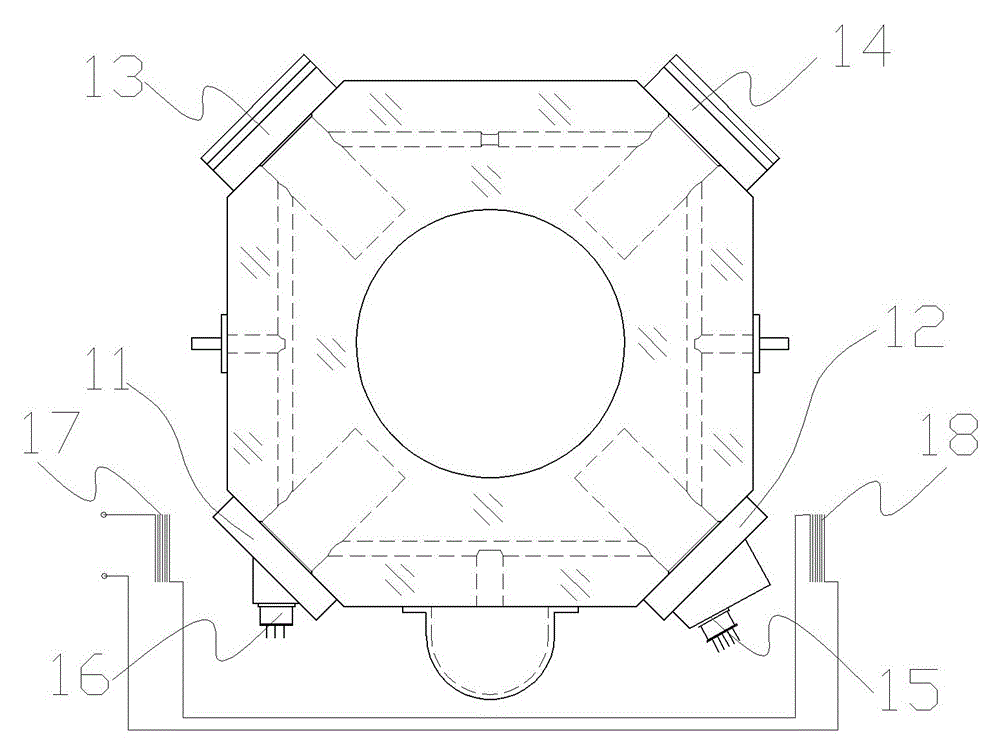
[0062] figure 2 It is a schematic diagram of a square two-frequency laser gyro with a coil installed outside the gyro cavity proposed by the present invention, which includes two plane mirrors 11, 12 and two optical path length control mirrors 13, 14, and the four mirrors form a ring Resonant cavity, gyro difference frequency signal output part 15, gyro light intensity signal output part 16, coils 17, 18 placed outside the gyro cavity for generating magnetic field.

[0063] The coils 17, 18 are installed together with the gyro cavity in the gyroscope. When using the alternating magnetic field method in the first embodiment, an alternating current is first applied to the coils 17, 18, and then the coils 17, 18 are subjected to technical means such as correlation detection or spectrum analysis. In the resolution of the change with frequency ω Size, using closed-loop measurement and control method, in the continuous acquisition of gyroscope In the case of gyro, the coplanar...

specific Embodiment 3

[0068] In the test room of the square two-frequency laser gyroscope before leaving the factory, the figure 2 The shown coil is installed outside the square two-frequency laser gyro outside the gyro cavity, using the method and method adopted in the second embodiment to obtain the optimal control parameters of the control voltage in the pitch direction on a group of optical path length control mirrors 13 and 14; Subsequently, only the gyro block is installed in the gyroscope, and the open-loop measurement and control method is used to measure a set of control voltage parameters for the minimum optical path length of the gyroscope to control the pitch angle of the mirror by using the above method, and use it as the implementation The normal working parameters of the gyroscope in the example, the optical path length control mirror of the gyroscope has been controlling the optical path of the gyroscope with these parameters.


PUM


Abstract

The invention discloses a method for reducing square two-frequency laser gyroscope magnetic sensitivity. The method includes the steps that a, at least two adjacent light path long control mirrors are installed in four reflectors on a square two-frequency laser gyroscope; b, an external magnetic field is initiatively applied to the laser gyroscope in a normal work state, and gyroscope difference frequency change caused by application of the external magnetic field is detected; c, angles of pitch of the two light path long control mirrors are controlled so as to adjust coplane degrees of a resonance light path of a gyroscope resonance cavity, the gyroscope difference frequency change caused by the external magnetic field is made to be the smallest and the state is kept finally. Compared with the prior art, the method is characterized in that path length control mirrors commonly used in the square two-frequency laser gyroscope in the prior art are replaced by light path long control mirrors, the angle control function of the control mirrors is utilized, gyroscope difference frequency signals serve as detection objects directly, non-coplanar angles of the resonance light path are reduced through adjustment, and therefore the purpose of reducing the square two-frequency laser gyroscope magnetic sensitivity can be achieved.

Description

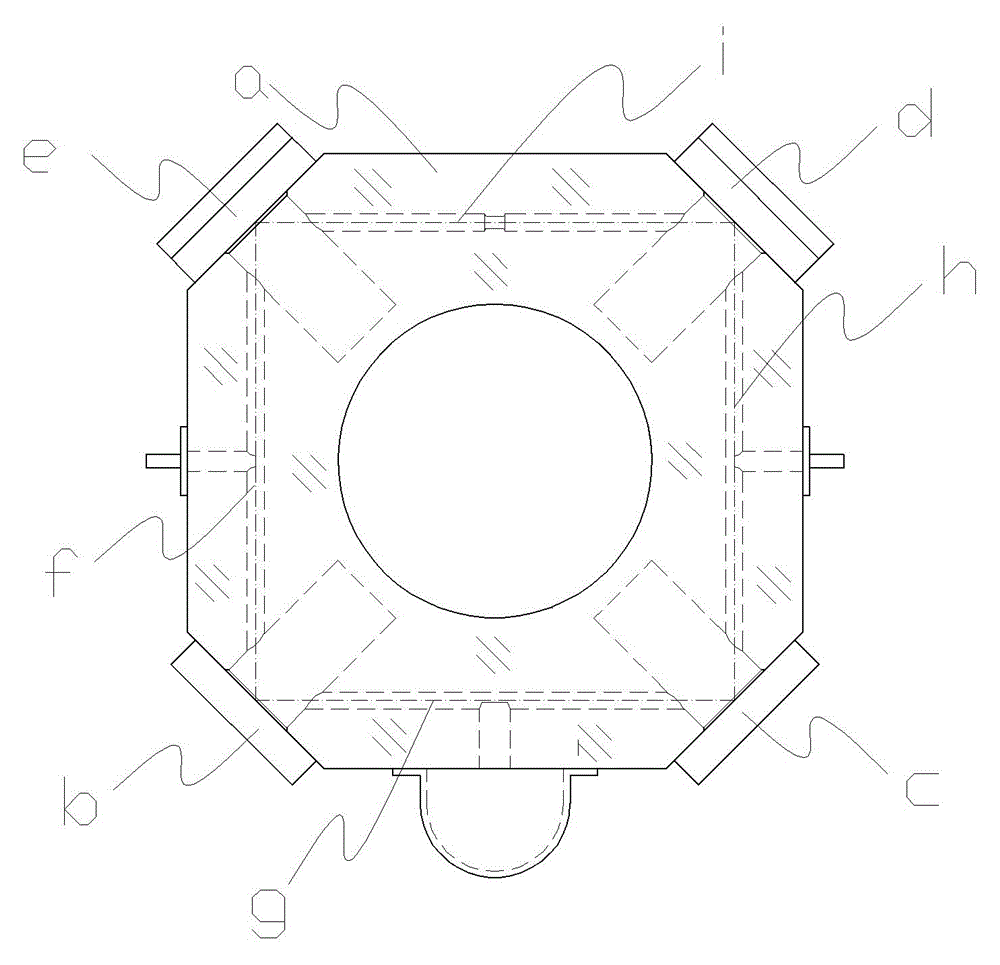
technical field [0001] The invention relates to an optical angular velocity sensing technology, in particular to a method for reducing the magnetic sensitivity of a square two-frequency laser gyroscope. Background technique [0002] The laser gyroscope is an angular velocity sensor based on the Sagnac effect. It reflects the magnitude of the input angular velocity through the resonance frequency difference of a pair of bidirectional traveling waves running in the ring resonator. One of them is a quadrilateral formed by four mirrors. Two-frequency laser gyro with ring resonant optical path (such as image 3 shown), its structure usually includes an octagonal gyro block a, on which are processed four patch surfaces supporting mirrors and capillary holes for passing light and filling the gain medium, two plane mirrors b, c and two spherical mirrors d and e optical glue form a ring resonant cavity on the four patch surfaces of the gyro block a; among them, the spherical mirrors ...

Claims


Application Information

Patent Timeline
Patent Type & Authority Patents(China)
IPC IPC(8): G01C19/66G01C25/00
Inventor 金世龙袁杰胡绍民滕庆华
Owner NAT UNIV OF DEFENSE TECH
Learn More