Phase selection switch verifying device and phase selection switch verifying method

A technology of phase selection switch and calibration device, which is applied in the direction of circuit breaker testing, etc., can solve the problems of cumbersome operation, large manpower consumption, and error-prone, so as to simplify the calibration work, improve the calibration efficiency, and avoid human errors Effect

Active Publication Date: 2013-12-04
江苏绿谊静风机设备有限公司
View PDF6 Cites 1 Cited by
  • Summary
  • Abstract
  • Description
  • Claims
  • Application Information

AI Technical Summary

Problems solved by technology

[0003] The switching time accuracy of the power frequency phase selection switch is required to be at the microsecond level, and special equipment is required to test the switching time accuracy, such as: switch tester, ampere-second characteristic tester, etc., plus peripheral interface equipment, such as the voltage divider It is inconvenient to operate and use; if you use a general-purpose oscilloscope and add peripheral equipment, it will take a lot of time to interpret the opening and closing, which is error-prone and cumbersome to operate.
[0004] Calibration of the phase selection switch is based on the inspection of the inherent action delay of each phase switch. According to the phase that needs to be opened and closed, manually calculate the time that needs to send the opening and closing control signal in advance, and use the computer to connect with the switch controller through the communication interface. Inputting the calculated time parameters on the computer also has the problems of labor-intensive, error-prone, and cumbersome operations
[0005] At present, there is no special equipment that can complete the inspection and calibration of the phase selection switch at the same time. The calibration of the phase selection switch is a manual process that uses a variety of equipment to inspect first and then calibrate.

Method used


Image

  • Phase selection switch verifying device and phase selection switch verifying method
  • Phase selection switch verifying device and phase selection switch verifying method
  • Phase selection switch verifying device and phase selection switch verifying method

Examples


Embodiment Construction

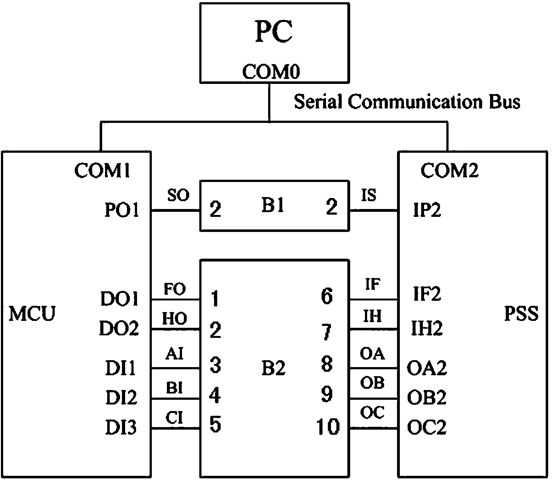
[0078] 1. A phase selection switch verification device, including a single-chip microcomputer MCU, a filter and isolation conversion circuit B1, an isolation circuit B2, a host computer PC and a three-phase phase selection switch PSS, see the attached figure 1 ;

[0079] The serial communication interface COM1 of the single-chip MCU and the serial communication interface COM2 of the three-phase phase selection switch PSS are connected with the serial communication interface COM0 of the upper computer PC;

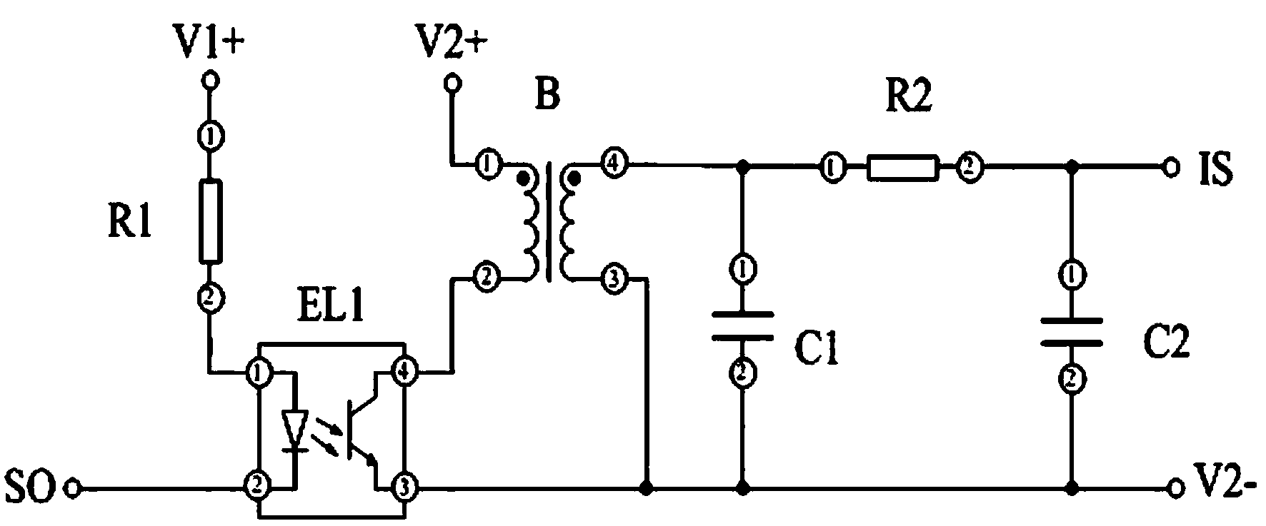
[0080] The PO1 interface of the single-chip MCU is connected to the signal input interface of the SO of the filtering and isolation conversion circuit B1, and the IS signal output interface of the filtering and isolation conversion circuit B1 is connected to the IP2 interface of the three-phase phase selection switch PSS;

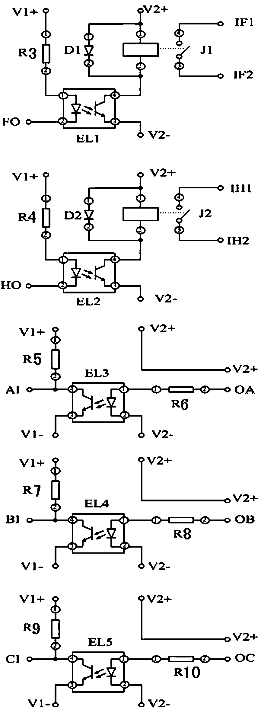
[0081] The D01, D02, D11, D12 and D13 interfaces of the MCU are respectively connected to the F0 signal input interface, the H0 signal input interface, t...


PUM


Abstract

The invention discloses a phase selection switch verifying device and a phase selection switch verifying method. The phase selection switch verifying device comprises a single chip microcomputer MCU, a smoothing and isolating changing circuit B1, an isolating circuit B2, an upper computer PC, a three-phase selection switch PSS, a serial communication interface of the single chip microcomputer MCU is connected with a serial communication interface of the three-phase selection switch PSS and a serial communication interface of the upper computer PC. A PO1 interface of the single chip microcomputer MCU is connected with an SO signal input interface of the smoothing and isolating changing circuit B1, an IS signal output interface of the smoothing and isolating changing circuit B1 is connected with an IP2 interface of the three-phase selection switch PSS, and D01, D02, D11, D12 and D13 interfaces of the single chip microcomputer MCU are respectively connected with corresponding interfaces of the isolating circuit B2. The method is used for manufacturing the special device for automatic verification, complex manual operation is not needed, therefore, man-made mistakes are avoided, and the verifying efficiency is improved.

Description

technical field [0001] The invention belongs to the technical field of electrical equipment automation, in particular to a phase selection switch calibration device and a phase selection switch calibration method. Background technique [0002] Phase selection switches, especially high-precision high-voltage three-phase AC switches, such as vacuum circuit breakers, can be calculated in advance according to the inherent delay of each phase switch's opening and closing action and the phases that need to be opened and closed. Time, and control the switch opening and closing according to this time, so as to realize the phase selection opening and closing of the switch at the specified phase. This kind of switch can be used in occasions that require phase selection, switching, switching of reactive power compensation capacitors, and switching of electrified railway power supplies. It can improve the transient process of the switching process, reduce the impact on the grid and equi...

Claims


Application Information

Patent Timeline
Patent Type & Authority Applications(China)
IPC IPC(8): G01R31/327
Inventor 张浩
Owner 江苏绿谊静风机设备有限公司
Why Eureka
Try Eureka