

Low-temperature charge and heating system and method for power battery for all-electric vehicles
A pure electric vehicle, power battery technology, applied in the direction of electric vehicle, secondary battery charging/discharging, secondary battery, etc., can solve the problems of low heating power, prolonged charging time, reduced system efficiency, etc. The effect of shortening heating time and improving system efficiency
- Summary
- Abstract
- Description
- Claims
- Application Information
AI Technical Summary
Problems solved by technology
Method used
Image

Examples
Embodiment Construction
[0020] The present invention will be further described below in conjunction with accompanying drawing.
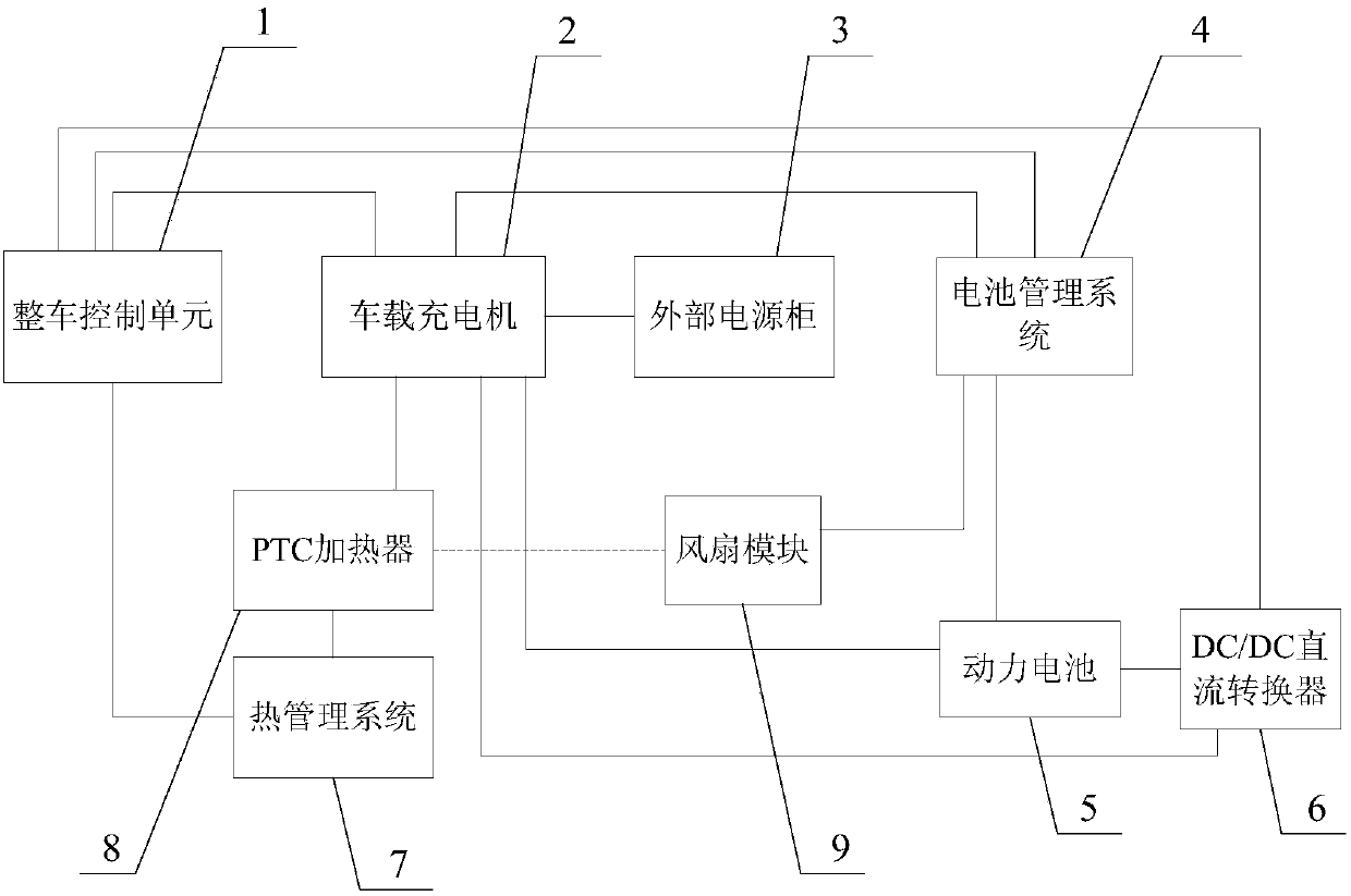
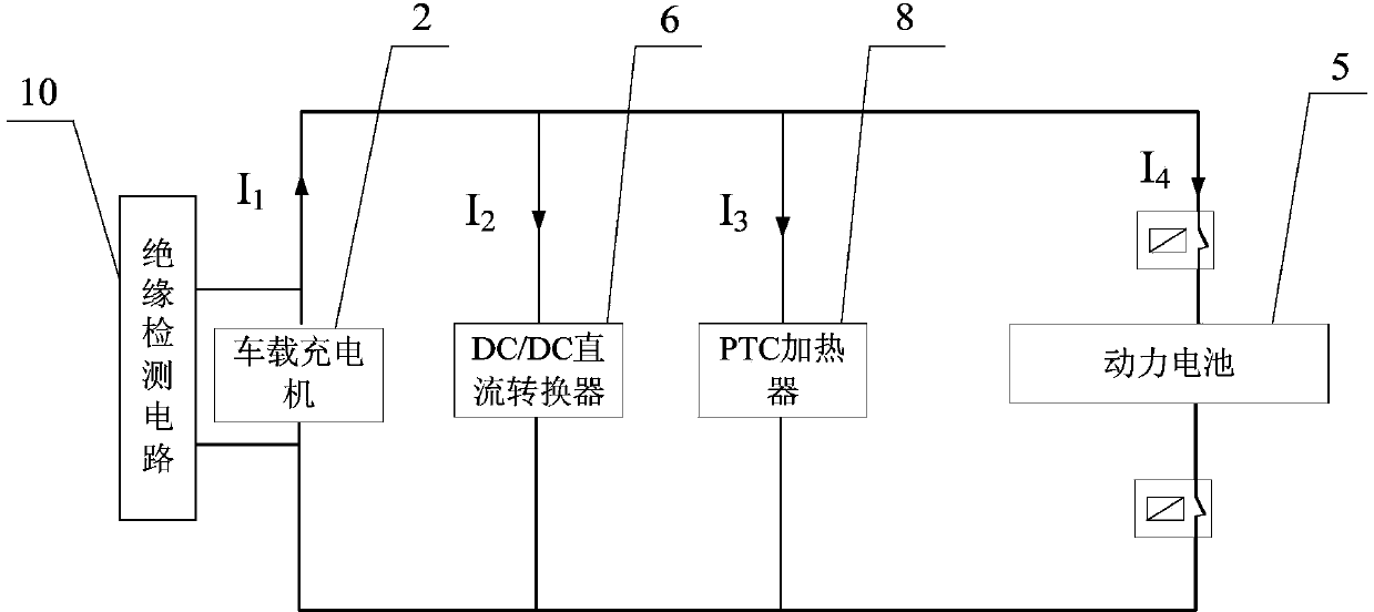
[0021] Such as figure 1 , figure 2 The low-temperature charging and heating system of the pure electric vehicle power battery shown includes the vehicle control unit 1, the on-board charger 2, the battery management system 4, the power battery 5, the DC / DC converter 6, the thermal management system 7, and the PTC heating system. 8 and a fan module 9, the on-board charger 2 is connected in parallel with an insulation detection circuit 10, and the fan module 9 is composed of a fan and a fan relay for controlling the fan to be powered on. The vehicle control unit 1 communicates with the on-board charger 2, battery management system 4, DC / DC converter 6, and thermal management system 7 to coordinate the on-board charger 2, battery management system 4, and DC / DC converter 6 , the work of the thermal management system 7; the on-board charger 2 is connected with the external po...
PUM
 Abstract
Description
Claims
Application Information