Eureka AIR delivers breakthrough ideas for toughest innovation challenges, trusted by R&D personnel around the world.

An interleaved parallel flyback led drive power supply and its pfm control circuit

A technology of LED driving and driving power, which is applied in the direction of electric lamp circuit layout, electric light source, control/regulation system, etc. It can solve the problems of large EMI of power supply, large switch stress, large current ripple, etc., and achieves increased conduction time, high The effect of power factor and operating frequency increase

Inactive Publication Date: 2015-09-02
JIANGSU UNIV
View PDF5 Cites 1 Cited by
  • Summary
  • Abstract
  • Description
  • Claims
  • Application Information

AI Technical Summary

Problems solved by technology

[0004] The present invention aims at the deficiencies existing in the actual use of the existing LED drive power supply, such as large switch stress, large power supply EMI, large current ripple, short power supply life, etc., and proposes an interleaved parallel flyback LED drive power supply and its The PFM control circuit makes the performance of the driving power supply greatly optimized

Method used


Image

  • An interleaved parallel flyback led drive power supply and its pfm control circuit
  • An interleaved parallel flyback led drive power supply and its pfm control circuit
  • An interleaved parallel flyback led drive power supply and its pfm control circuit

Examples


Embodiment Construction

[0017] The present invention will be further described below in conjunction with the accompanying drawings.

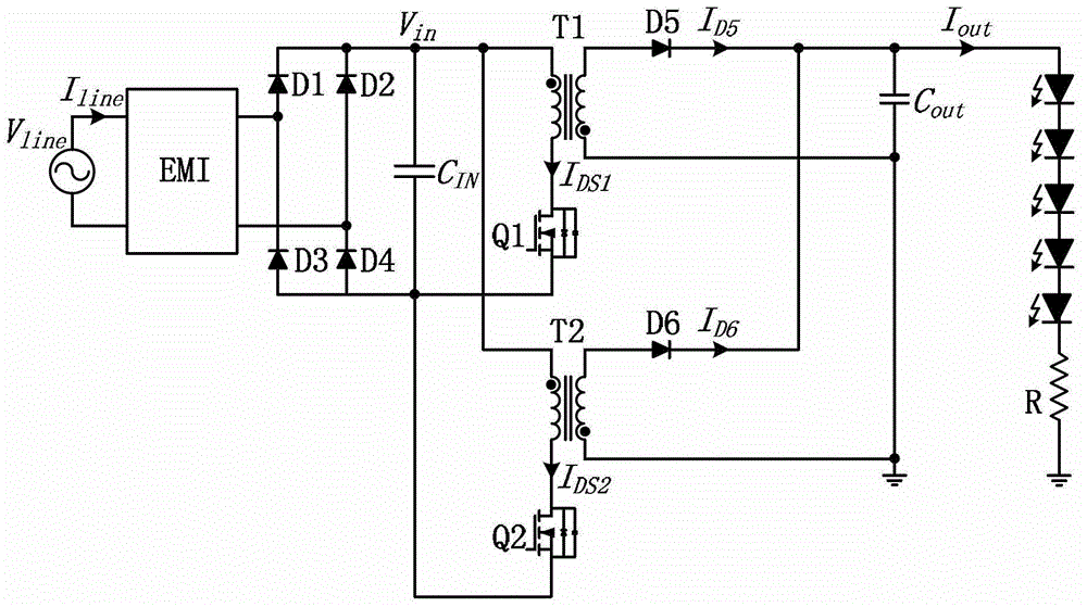
[0018] see figure 1 It is the main power circuit diagram of the present invention, the AC mains input is connected to the rectifier bridge composed of diodes D1, D2, D3, D4 through the EMI filter, and its positive pole output is respectively connected to one end of the primary winding of the transformer T1, T2, and the primary winding of the transformer T1 The other end is connected to the drain of the switch tube Q1, and the source of the switch tube Q1 is connected to the negative pole of the rectifier bridge; one end of the secondary winding of the transformer T1 is connected to the anode of the output rectifier diode D5, and the cathode of the output rectifier diode D5 is connected to the output rectifier diode D6. Cathode, output capacitor C out One end of the transformer T1 secondary winding is connected to one end of the LED load, and the other end of the secon...


PUM


Abstract

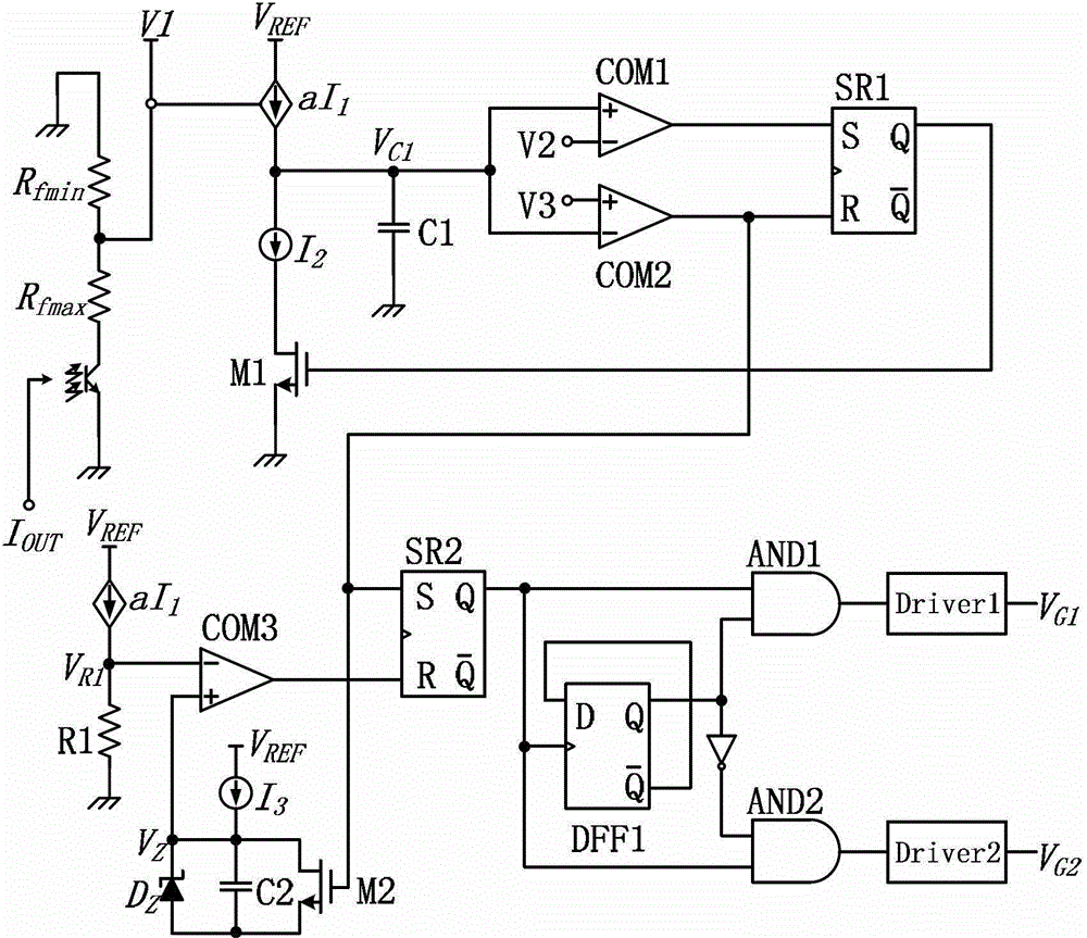
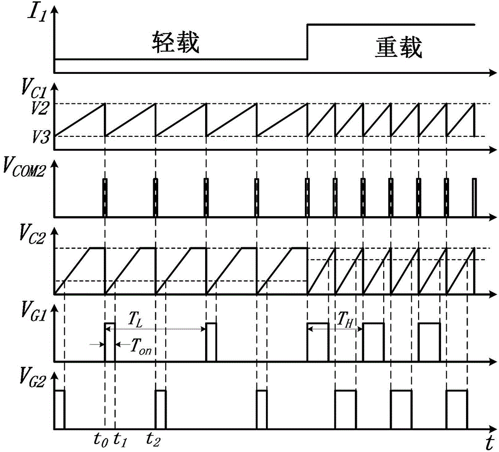
The invention discloses a staggered parallel flyback LED driving power supply and a PFM (pulse width modulation) control circuit thereof. A main circuit of the driving power supply is formed by staggering and parallel connection of two flyback converters, and comprises an alternating-current input end, an EMI (electromagnetic interference) filter, a bridge rectifier, the two parallel flyback converters, an output rectifier and an LED load. By the aid of the staggered parallel main circuit structure, current stress of switching tubes is reduced, input and output current ripple is reduced, the EMI filter design is simplified, power level of the driving power supply is increased, and the like. A PFM control method is adopted in the control circuit of the driving power supply; compared with a common PWM control method, the PFM control method has the advantages that by the aid of the PFM control circuit, the driving power supply can change in switching tube turning-on time and switching frequency simultaneously when the load changes, working loss during light load of the driving power supply is reduced, and power supply efficiency is improved. The driving power supply is suitable for applications of an LED driving power supply with an automatic dimming function.

Description

technical field [0001] The invention belongs to the technical field of power electronics applications, and in particular relates to an interleaved parallel flyback LED drive power supply and a PFM control circuit thereof, which are suitable for switching power supplies, especially in the application field of LED drive power supplies. Background technique [0002] Switching power supply is an indispensable power electronic device in modern social life, and it has a very wide range of applications in the fields of electronics, communications, electricity, energy, lighting, aerospace, military and home appliances. With the further development of power electronics technology, the society has further increased the requirements for the volume, reliability, cost, energy saving and environmental protection of switching power supply. In recent years, with the maturity of LED lighting technology, LED driving power supply has become a research hotspot. More and more countries and organ...

Claims


Application Information

Patent Timeline
Patent Type & Authority Patents(China)
IPC IPC(8): H02M3/335H02M1/088H02M1/14H02M1/42H05B37/02
CPCY02B70/10
Inventor 廖志凌王生东梅从立陈兆岭
Owner JIANGSU UNIV
Why Eureka
Eureka Blog
Learn More