Digital signal transmitting device and receiving device as well as digital signal modulation method and demodulation method

A digital signal transmission and digital signal technology, which is applied in the field of digital signal transmitting devices and receiving devices, can solve problems such as performance loss, unfavorable equalization algorithm, and error correction code method to increase system complexity, so as to improve performance, realize flexibility, The effect of reducing system complexity

Active Publication Date: 2013-12-04
SHANGHAI NAT ENG RES CENT OF DIGITAL TELEVISION
View PDF5 Cites 14 Cited by
  • Summary
  • Abstract
  • Description
  • Claims
  • Application Information

AI Technical Summary

Problems solved by technology

[0004] 1. For the transmitter and receiver, the diversity of error correction codes increases the complexity of the system more or less
[0005] 2. For the equalization part of a single-carrier system, if decision feedback or similar techniques are used, the higher-order constellation point mapping is more unfavorable to the equalization algorithm. For example, the decision feedback gain of 256QAM is smaller than that of 64QAM, but when higher When the code rate is high, you have to use high-order constellation point mapping
[0006] 3. The QAM mapping of the odd power of 2, such as 32QAM and 128QAM, cannot fully satisfy the conditions of Gray mapping, so there will be performance loss

Method used


Image

  • Digital signal transmitting device and receiving device as well as digital signal modulation method and demodulation method
  • Digital signal transmitting device and receiving device as well as digital signal modulation method and demodulation method
  • Digital signal transmitting device and receiving device as well as digital signal modulation method and demodulation method

Examples


Embodiment Construction

[0025] The technical solutions of the present invention will be further described below in conjunction with the accompanying drawings and embodiments.

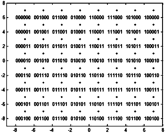
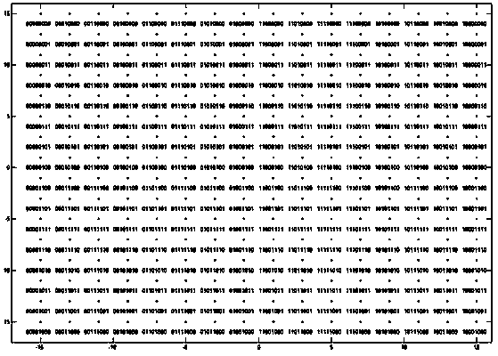
[0026] In order to reduce the diversity of error correction codes and avoid the use of mapping methods such as 32QAM and 128QAM, the present invention discloses a communication system and a communication method, in which there are transmitting devices, receiving devices corresponding to the transmitting devices and their respective modulation method and demodulation method.

[0027] Such as figure 1 As shown, the transmitting device of the present invention has an error correction code encoder 11 , a code stream grouping module 12 , a first constellation point mapping module 13 , a second constellation point mapping module 14 and a symbol interleaver 15 connected in sequence. The following describes the modulation method of the transmitting device and the functions and signal transmission of each module in accordance with the...


PUM


Abstract

The invention discloses a digital signal transmitting device and a digital signal receiving device as well as a digital signal modulation method and a digital signal demodulation method. The digital signal transmitting device and the digital signal receiving device of the invention are characterized in that the digital signal transmitting device and the digital signal receiving device comprise a plurality of constellation point mapping modules and a plurality of constellation point de-mapping modules respectively; and different QAM mapping is adopted between each mapping module and each de-mapping module. The digital signal modulation method and the digital signal demodulation method of the invention are characterized in that one code stream is divided into a plurality of sub code streams which are subjected to mapping, and correspondingly, one baseband symbol stream is divided into a plurality of symbol streams which are subjected to de-mapping. With the digital signal transmitting device and receiving device as well as the digital signal modulation method and demodulation method of the invention adopted, according to problems such as too many error-correcting code modes and performance loss of modulation modes such as 32QAM and 128QAM, the flexibility of code rate and receiving threshold can be realized through the modulation modes of hybrid constellation points, and therefore, the complexity of a system can be decreased, and performance can be improved.

Description

technical field [0001] The present invention relates to a modulation and demodulation device and a corresponding method of a communication system, more specifically, to a digital signal transmitting device, a receiving device and a corresponding modulation and demodulation method. Background technique [0002] Existing communication systems, such as DVB-T2 and DTMB, have many different modulation modes and error correction code modes in order to meet different code rate and receiving threshold requirements. For example, DTMB has different modulation modes such as QPSK, 16QAM, 32QAM and 64QAM, and three different LDPC modes of 0.4, 0.6 and 0.8. But DTMB has only one modulation method in any mode. Different channels of DVB-T2 can use different modulation methods, but only one modulation method will be used for the same service flow. [0003] Such a system has the following problems: [0004] 1. For the transmitting end and the receiving end, the diversity of error correcti...

Claims


Application Information

Patent Timeline
Patent Type & Authority Applications(China)
IPC IPC(8): H04L27/36H04L27/38
Inventor 张文军管云峰史毅俊王延峰王尧何大治徐胤杨帆
Owner SHANGHAI NAT ENG RES CENT OF DIGITAL TELEVISION
Why Eureka
Try Eureka