
Layered liquid settling tank for production sewage of modifying agent

A technology for the production of sewage and modifiers, applied in the direction of settlement tanks, etc., can solve the problems of high maintenance costs, delay in production, and large floor area, and achieve the effect of reducing the content of settleables and improving settlement, and occupying a small area Effect

Inactive Publication Date: 2013-12-11
NANJING CONCORD FERTILIZER CHEM
View PDF4 Cites 3 Cited by
  • Summary
  • Abstract
  • Description
  • Claims
  • Application Information

AI Technical Summary

Problems solved by technology

[0002] The settling tank is a commonly used equipment for settling and purifying the flocculent or granular substances that can settle down in the separation liquid. It is widely used in sewage purification. The traditional settling tank is a sloping plate. The sloping plate in the settling tank is usually a single Laminates allow the liquid to pass through multiple sloping plates in sequence. Many settling spaces are spread out in parallel and occupy a large area. When the water flow to be settled is large, the sloping plates are easily deformed by impact, and the settling tank needs to be maintained frequently. The cost is high, and the settling tank is usually used in sewage treatment, which is a continuous and uninterrupted process. In many production-oriented enterprises, the maintenance of the settling tank is a very cumbersome matter that delays production and affects the profitability of the enterprise.

Method used


Image

  • Layered liquid settling tank for production sewage of modifying agent

Examples


Embodiment Construction

[0011] The present invention will be further explained below in conjunction with the accompanying drawings and specific embodiments. It should be understood that the following specific embodiments are only used to illustrate the present invention but not to limit the scope of the present invention. It should be noted that the words "front", "rear", "left", "right", "upper" and "lower" used in the following description refer to the directions in the drawings, and the words "inner" and "outer ” refer to directions towards or away from the geometric center of a particular part, respectively.

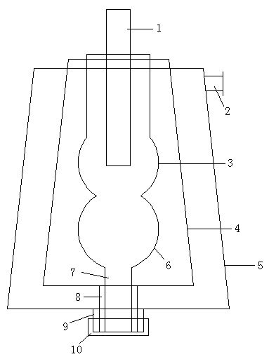
[0012] It can be seen in conjunction with the accompanying drawings that the laminar liquid settling tank used for the production of sewage by this modifier comprises a liquid inlet pipe 1, a liquid inlet tank 3, an intermediate tank 4 and an outer layer tank 5, and a sediment tank 6 is provided below the liquid inlet tank 3 for feeding The liquid tank 3 and the sediment tank 6 are suspend...


PUM


Abstract

The invention discloses a layered liquid settling tank for production sewage of a modifying agent. A sediment tank is arranged under a liquid feeding tank, the liquid feeding tank and the sediment tank are positioned inside an intermediate tank in a suspending manner, the intermediate tank is positioned inside an outer layer tank in a suspending manner, the caliber of a part in which the liquid feeding tank is connected and communicated with the sediment tank is reduced, the liquid feeding tank and the sediment tank lead to respective centers from the part in which the liquid feeding tank is connected and communicated with the sediment tank, the calibers of the liquid feeding tank and the sediment tank are smoothly enlarged, an inner deslagging pipe, an intermediate deslagging pipe and an outer deslagging pipe which are concentric are respectively arranged at bottom ends of the sediment tank, the intermediate tank and the outer layer tank, lower ends of the inner deslagging pipe, the intermediate deslagging pipe and the outer deslagging pipe are aligned, a blanking cap is arranged outside the outer deslagging pipe, the lower end of the liquid feeding pipe extends to the center of the liquid feeding tank, and a liquid discharging pipe is arranged on the side wall of the upper end of the outer layer tank. The layered liquid settling tank is compact in structure and small in occupation area; and a plurality of settling space devices are overlapped up an down, liquid slowly overflows from the settling tank at the innermost layer to the settling tank at the outer layer, thus the occupation area of the device is greatly reduced, and the settling effect is better.

Description

technical field [0001] The invention relates to a layered liquid settling tank for producing sewage with a modifier, which is a settling device formed by interlocking the inside and outside of the multi-layered settling tank, belonging to the field of chemical equipment. Background technique [0002] The settling tank is a commonly used equipment for settling and purifying the flocculent or granular substances that can settle down in the separation liquid. It is widely used in sewage purification. The traditional settling tank is a sloping plate. The sloping plate in the settling tank is usually a single Laminates allow the liquid to pass through multiple sloping plates in sequence. Many settling spaces are spread out in parallel and occupy a large area. When the water flow to be settled is large, the sloping plates are easily deformed by impact, and the settling tank needs to be maintained frequently. The cost is high, and settling tanks are usually used in sewage treatmen...

Claims


Application Information

Patent Timeline
Patent Type & Authority Applications(China)
IPC IPC(8): B01D21/02
Inventor 黄艳
Owner NANJING CONCORD FERTILIZER CHEM
Learn More