Electrode cap overlay welding device with automation function

An electrode cap and function technology, which is applied in the field of spot welding electrode processing machinery, can solve the problems of unsatisfactory efficiency, high work intensity of workers, and high fusion efficiency, so as to reduce the intensity of surfacing work, save labor resources, reduce The effect of labor costs

Inactive Publication Date: 2013-12-11
苏州飞泰精工科技有限公司
View PDF17 Cites 4 Cited by
  • Summary
  • Abstract
  • Description
  • Claims
  • Application Information

AI Technical Summary

Problems solved by technology

[0007] The fused titanium carbide on the surface of the electrode cap mentioned above is surfacing welding titanium carbide (hereinafter the same), in view of the fact that there is no such method used to fused titanium carbide on the end surface of the point electrode cap in the published patents and non-patent literature so far. Due to the technical inspiration of the special device, workers usually hold the welding torch to fuse the transition metal rod (rod-shaped) clamped on the welding torch to the end face of the electrode cap. However, due to the special shape of the electrode cap (like a hollow one It has the shape of a bullet head with a conical blind hole), so it is very troublesome to clamp it reliably unless a complex and unique fixture device is used; Reliable clamping, then the worker needs to make the welding torch frequently move 360° around the electrode cap (circling action) during melting, which leads to the worker's work intensity is high, and the efficiency is not flattering; also because if the clamping and The longer the process of releasing the electrode cap, the greater the impact on the melting efficiency, which makes it difficult to meet the requirements of industrial scale-up production; and in order to adapt to the requirements of industrial production, more surfacing workers have to be invested, resulting in both Waste of labor resources leads to increased manufacturing costs

Method used


Image

  • Electrode cap overlay welding device with automation function
  • Electrode cap overlay welding device with automation function

Examples


Embodiment Construction

[0023] In order to enable the examiners of the patent office, especially the public, to understand the technical essence and beneficial effects of the present invention more clearly, the applicant will describe in detail the following in the form of examples, but none of the descriptions to the examples is an explanation of the solutions of the present invention. Any equivalent transformation made according to the concept of the present invention which is merely formal but not substantive shall be regarded as the scope of the technical solution of the present invention.

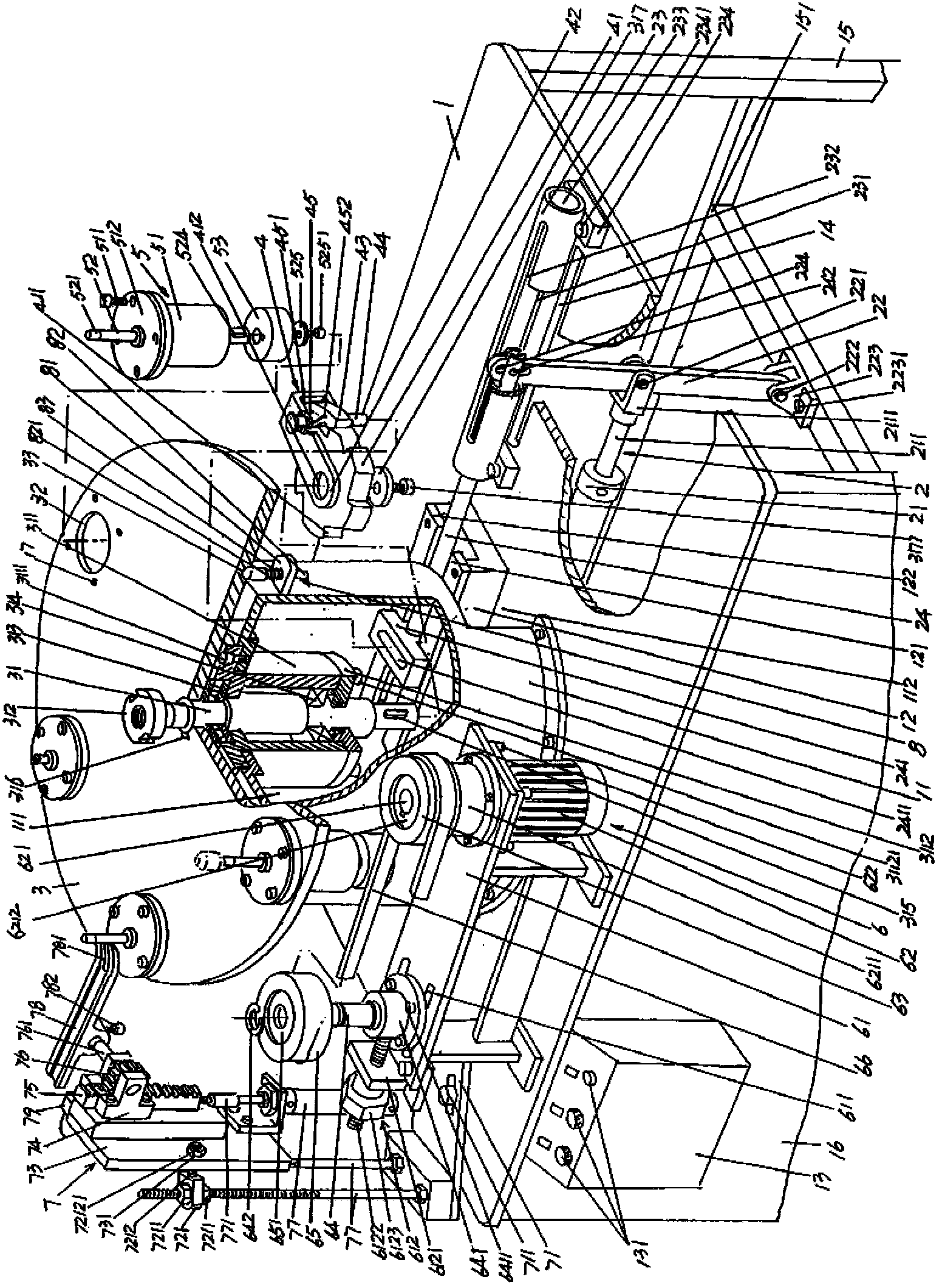
[0024] In the following descriptions, all orientation concepts such as up, down, left, right, front, and back are based on the current figure 1 As far as the positional state shown is concerned, it should not be understood as a specific limitation of the solution of the present invention.

[0025] See figure 1 , provides a workbench 1, the shape of the workbench 1 is a rectangular shape, the present embodime...


PUM


Abstract

The invention relates to an electrode cap overlay welding device with an automation function and belongs to the technical field of spot-welding electrode manufacturing machinery. The electrode cap overlay welding device comprises a workbench, a pawl shaft driving mechanism, a rotary disc, a rotary disc shaft driving mechanism, a group of electrode cap pivoting support mechanisms, a power transmission mechanism and an automatic electrode cap expelling mechanism, wherein a tubular seat and a guide rail seat are fixedly arranged on the workbench, a push rod yielding chamber is formed at one side, facing to the pawl shaft driving mechanism, of the tubular seat, and the pawl shaft driving mechanism is arranged on the workbench and is matched with the guide rail seat; a rotary disc shaft is fixedly arranged at the center of the rotary disc and supports the tubular seat, and the lower end of the rotary disc shaft extends into a tubular seat chamber; the rotary disc shaft driving mechanism is fixedly connected with the lower end of the rotary disc shaft; the electrode cap pivoting support mechanisms are equidistantly distributed around the edge positions of the rotary disc in a spaced manner; the power transmission mechanism is arranged on the workbench; the automatic electrode cap expelling mechanism is arranged on the workbench and is matched with the electrode cap pivoting support mechanisms. The electrode cap overlay welding device with the automation function has the advantages that the dependence on clamping devices of complicated structures is not required; the intensity of overlay welding operation is reduced; an ideal automatic effect can be embodied; the labor cost is reduced.

Description

technical field [0001] The invention belongs to the technical field of spot welding electrode processing machinery, and in particular relates to an electrode cap surfacing welding device with automatic function. Background technique [0002] The aforementioned electrode cap is the spot welding electrode, which is widely used in various welding equipment such as spot welding machines, resistance welding pliers, etc. The welding equipment that heats the junction of two workpieces to be welded to a plasticized state or partially melted state due to the difference in resistance calorific value, and forms a firm joint under pressure, is used in vehicles, aircraft, ships, electromechanical products, etc. It is widely used in production, even widely used in the production of power transmission and transformation devices such as transformer cooling fins. For details, please refer to the Chinese invention patent application publication numbers CN102528262A, CN102554527A, CN102528351A...

Claims


Application Information

Patent Timeline
Patent Type & Authority Applications(China)
IPC IPC(8): B23K9/12B23K9/04B23K37/04
Inventor 顾祖良
Owner 苏州飞泰精工科技有限公司
Why Eureka
Try Eureka