Horizontal suspension sludge air-lift backflow method

A technique of suspended sludge and airlift reflux, applied in water/sludge/sewage treatment, chemical instruments and methods, biological water/sewage treatment, etc. The method cannot efficiently complete the reflow task, the area is large, etc., to achieve the effect of long reflow route, ensuring consistency, and high energy consumption

Active Publication Date: 2013-12-11
CENT & SOUTHERN CHINA MUNICIPAL ENG DESIGN & RES INST
View PDF4 Cites 2 Cited by
  • Summary
  • Abstract
  • Description
  • Claims
  • Application Information

AI Technical Summary

Problems solved by technology

These methods are not suitable for the balanced and timely return of a large-area suspended activated sludge layer. The main reason is that the suspended activated sludge layer is located in the upper middle of the pool, with a large area and far away from the bottom of the pool. Hydraulic mechanical methods and point methods Air stripping methods cannot efficiently complete the reflux task

Method used


Image

  • Horizontal suspension sludge air-lift backflow method
  • Horizontal suspension sludge air-lift backflow method
  • Horizontal suspension sludge air-lift backflow method

Examples


Embodiment 1

[0026] In the following, the present invention will be further described by referring to the accompanying drawings and using the horizontal suspended sludge airlift and reflux method of the present invention as an example in conjunction with an activated sludge process sewage treatment tank.

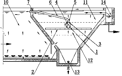
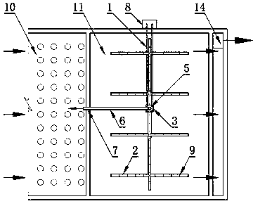
[0027] From figure 1 and figure 2 It can be seen from the figure that this reflux method adopts the surface-type air-lift reflux device applied for at the same time, which is mainly composed of a horizontal air inlet pipe 1, a closed suction pipe 2 connected horizontally and vertically, and a surrounding airtight airtight pipe located above the middle of the suction pipe. The box body 3, the air nozzle 4 located in the box body, the standpipe elbow 5, the return inclined pipe 6, and the return flow through the wall pipe 7 are composed, and are controlled by the compressed air control device 8 outside the pool.

[0028]The mud-water mixture from the biochemical treatment tank 10 enters ...

Embodiment 2

[0031] The sewage treatment capacity of a sewage treatment plant is 12,000 m 3 / d, there are 2 towers of 6000m each 3 / d V-type air-lifting integrated sewage treatment tank, the horizontal suspended sludge air-lifting and reflux method of the present invention is used to reflux the suspended activated sludge in the clarification area of ​​the integrated treatment tank, and a total of 2 sets of surface-type air-lifting Micro power reflux device, each set consumes 0.995m of air 3 / min, the converted blower power consumption is 1.456Kw (single blower parameter Q=16.67 m 3 / min, P=58.8kPa, equipped with a 30kW motor with a frequency conversion device, the actual shaft power is 24. 4kW), and a good activated sludge return effect and sewage treatment effect have been obtained. The water quality is shown in the table below.

[0032] Sewage treatment plant design inlet and outlet water quality table

[0033] project COD BOD 5 SS TN NH 3 -N TP Influent ...


PUM


Abstract

The invention provides a horizontal suspension sludge air-lift backflow method. The method mainly comprises the following steps: sludge is sucked completely and in equilibrium and lifted to a biochemical reaction tank for recycling by arranging a horizontal plane-type air-lift micro-power backflow device in a suspension thick activated sludge layer and utilizing sludge suction pipes of the backflow device, which are horizontally arranged in the vertical and horizontal directions, and a compressed air control device outside the tank adjusts the air volume to control the quantity of backflow. Compared with the conventional sludge backflow method, the horizontal suspension sludge air-lift backflow method provided in the invention has a high backflow efficiency, there is no dead area or dead angle of sludge return in the large-area suspension sludge layer, and the backflow is in equilibrium; and besides, the activated sludge floc structure is not damaged, the control of backflow quantity is flexible, rapid and visual, no moving part or electrical equipment is used under water, and the backflow reliability is extremely high. Furthermore, an aeration blower of a sewage treatment plant is adopted for air supply, the corrected energy consumption for air-lift backflow is extremely low, and the energy-saving effect is obvious.

Description

technical field [0001] The present invention relates to a method for airlifting and reflux of horizontal suspended sludge, especially utilizing the principle of airlifting and the uniform structure of perforated suction pipes on the horizontal plane to realize the comprehensive and balanced lifting of activated sludge with extremely low lift. Bring back the flow method. Background technique [0002] Among the current sewage treatment methods, the activated sludge method is still the most widely used secondary biological treatment process in the world. After the sewage undergoes secondary biochemical treatment through the aeration tank, it generally needs to enter the secondary sedimentation tank for mud-water separation, clean water disinfection and discharge, and the settled sludge is returned to the aeration tank for reuse through the sludge return pump, and a small part of the sludge Concentrated and dehydrated as excess sludge. In the early days, the activated sludge r...

Claims


Application Information

Patent Timeline
Patent Type & Authority Applications(China)
IPC IPC(8): C02F3/00
Inventor 刘贤斌李路刘学阳
Owner CENT & SOUTHERN CHINA MUNICIPAL ENG DESIGN & RES INST
Why Eureka
Try Eureka