Novel stirrup shearing connector as well as manufacturing and installing methods thereof

An installation method and a technology of connectors, which are applied to building components, floor slabs, buildings, etc., can solve the problems of brittle failure of perforated steel plate connectors, high construction requirements of bent steel bar connectors, and poor deformation resistance. Improve the vertical shear capacity, increase the ability to deform plastically, and improve the effect of shear strength and stiffness

Inactive Publication Date: 2013-12-11
NANJING TECH UNIV
View PDF3 Cites 5 Cited by
  • Summary
  • Abstract
  • Description
  • Claims
  • Application Information

AI Technical Summary

Problems solved by technology

[0007] The purpose of the embodiments of the present invention is to provide a new type of stirrup shear connector and its preparation and installation method, aiming at solving the problem of poor deformation resistance of existing stud connectors, high steel consumption of section steel shear connectors and welding residues Stress, open-hole steel plate connectors are prone to brittle failure, and bent steel bar connectors have high construction requirements

Method used


Image

  • Novel stirrup shearing connector as well as manufacturing and installing methods thereof
  • Novel stirrup shearing connector as well as manufacturing and installing methods thereof
  • Novel stirrup shearing connector as well as manufacturing and installing methods thereof

Examples


Embodiment Construction

[0036] In order to make the objectives, technical solutions and advantages of the present invention clearer, the present invention will be further described in detail below in conjunction with embodiments. It should be understood that the specific embodiments described herein are only used to explain the present invention, but not to limit the present invention.

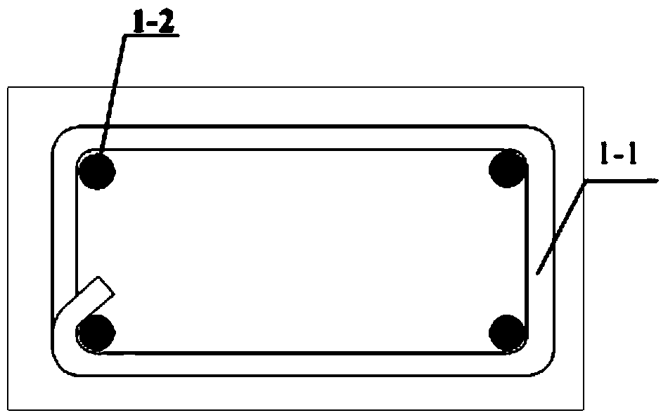
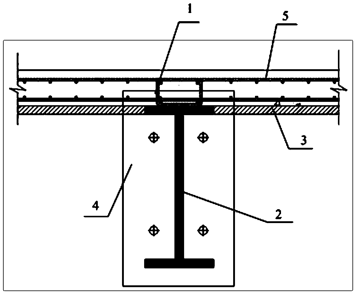
[0037] Such as figure 1 As shown, the novel stirrup shear connector of the embodiment of the present invention is mainly composed of stirrup shear connector 1, stirrup 1-1, longitudinal reinforcement 1-2, steel beam 2, template 3, end plate 4, and transverse reinforcement 5 composition; the cross section of stirrup 1-1 is rectangular, the longitudinal reinforcement 1-2 is placed inside the stirrup 1-1 and tied to the four corners of the stirrup 1-1, and the stirrup 1-1 is welded to the upper flange of the steel beam 2. Together; the template 3 is set on the upper part of the end plate 4, the stirrup shear connector 1 is...


PUM


Abstract

The invention discloses a novel stirrup shearing connector as well as manufacturing and installing methods of the novel stirrup shearing connector. The connector comprises a stirrup shearing connector, a stirrup, longitudinal reinforcing steel bars, a steel beam, a template, end plates and transverse reinforcing steel bars. The manufacturing and installing methods comprise the following steps: manufacturing the steel beam and the stirrup and welding the component, placing the longitudinal reinforcing steel bars at four corners inside the stirrup to complete binding; hoisting the structure; binding the reinforcing the steel bars by a floorboard supporting and protecting template; casting concrete; normally maintaining the concrete and then dismounting the template. According to the invention, a steel reinforcement cage which is bound by the longitudinal reinforcing steel bars and the stirrup is welded with the upper wing edge of the steel beam, and then bound with the transverse and the longitudinal reinforcing steel bars in a concrete plate to form an integer, so that the shearing resistance and rigidity of the steel beam-concrete combined component are effectively improved, thereby achieving cooperative stress of the concrete and the steel beam, a simple structure and convenience in construction, restricting lifting deformation, increasing plasticity (i.e., deformable capacity) of the concrete and the steel beam, and improving the stability and the reliability of the concrete and the steel beam.

Description

Technical field [0001] The invention belongs to the technical field of steel-concrete composite beam connectors, and particularly relates to a novel stirrup shear connector and a preparation and installation method. Background technique [0002] The steel-concrete composite beam is a flexural member that connects steel beams and concrete slabs into a whole through shear connectors. Shear connectors are the key components of steel-concrete composite beams. They have two main functions: one is to withstand and transmit the longitudinal shear between the steel beam and the concrete slab; the other is to resist the difference between the concrete slab and the steel beam. The flipping of time works. Generally speaking, shear connectors can be divided into rigid connectors and flexible connectors. Specifically, they can be divided into the following four types: stud connectors, bent steel reinforcement connectors, section steel shear connectors, and holes Steel plate connector. [000...

Claims


Application Information

Patent Timeline
Patent Type & Authority Applications(China)
IPC IPC(8): E04B5/29E04G21/00E04B1/38
Inventor 胡夏闽徐晓晖唐伟
Owner NANJING TECH UNIV
Why Eureka
Try Eureka