Supercharge Your Innovation With Domain-Expert AI Agents!

Installation method for wall grounding plate

An installation method and site technology, which are applied in the direction of connecting contact materials, buildings, building structures, etc., can solve the problems of failure of the support system, deep sinking of the casting ground plate 2, and failure to find it, so as to shorten the installation time and reduce the construction time. cost, the effect of improving the quality of installation

Active Publication Date: 2013-12-11
SHANGHAI NUCLEAR ENG RES & DESIGN INST CO LTD
View PDF4 Cites 0 Cited by
  • Summary
  • Abstract
  • Description
  • Claims
  • Application Information

AI Technical Summary

Problems solved by technology

[0004] First, the fixed support system composed of welded steel support 3 and steel bar 5 is easily affected by external forces such as concrete pouring disturbance and construction personnel's climbing support during the construction process, resulting in the depression, displacement and inclination of the casting grounding plate 2
[0005] Second, the establishment of template 6 leads to the depression of casting ground plate 2
The gap between the template 6 and the installed cast grounding plate 2 is relatively large. After the concrete pouring is completed, the casting grounding plate 2 is covered by concrete, and the pre-buried casting grounding plate 2 cannot be found from the wall surface, resulting in the casting grounding plate 2 recessed in the wall
[0006] Third, the concrete is prone to slight expansion during the pouring process, which causes some areas on the surface of the wall to bulge, thus causing the casting grounding plate 2 to sink deep into the wall after pouring
[0007] Fourth, when the formwork 6 is set up, it is easy to crush the support pad behind the fixed support system of the casting grounding plate 2, resulting in the failure of the support system, and finally causing the casting grounding plate 2 to tilt, shift, and sag after the concrete is poured

Method used


Image

  • Installation method for wall grounding plate
  • Installation method for wall grounding plate
  • Installation method for wall grounding plate

Examples


Embodiment Construction

[0023] In order to make the present invention more comprehensible, preferred embodiments are described in detail below with accompanying drawings.

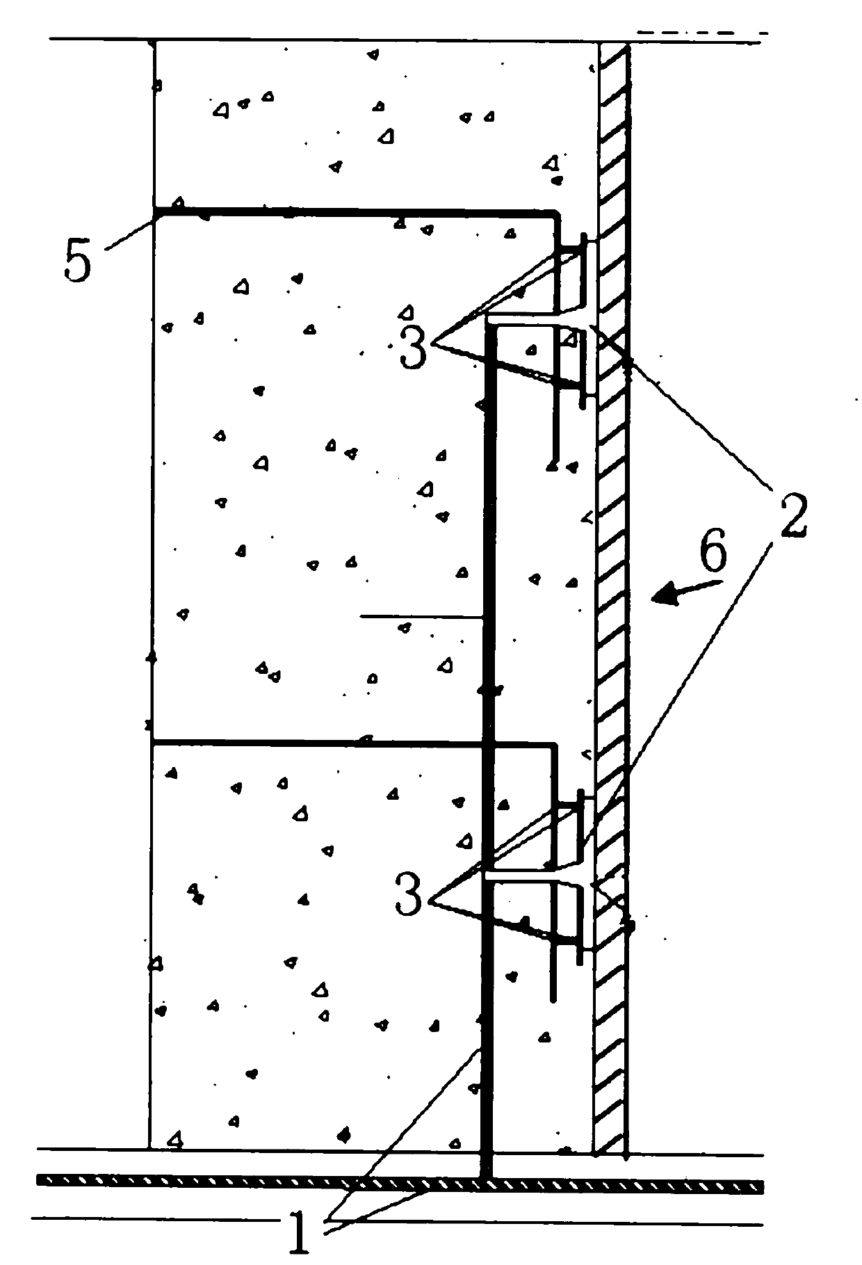
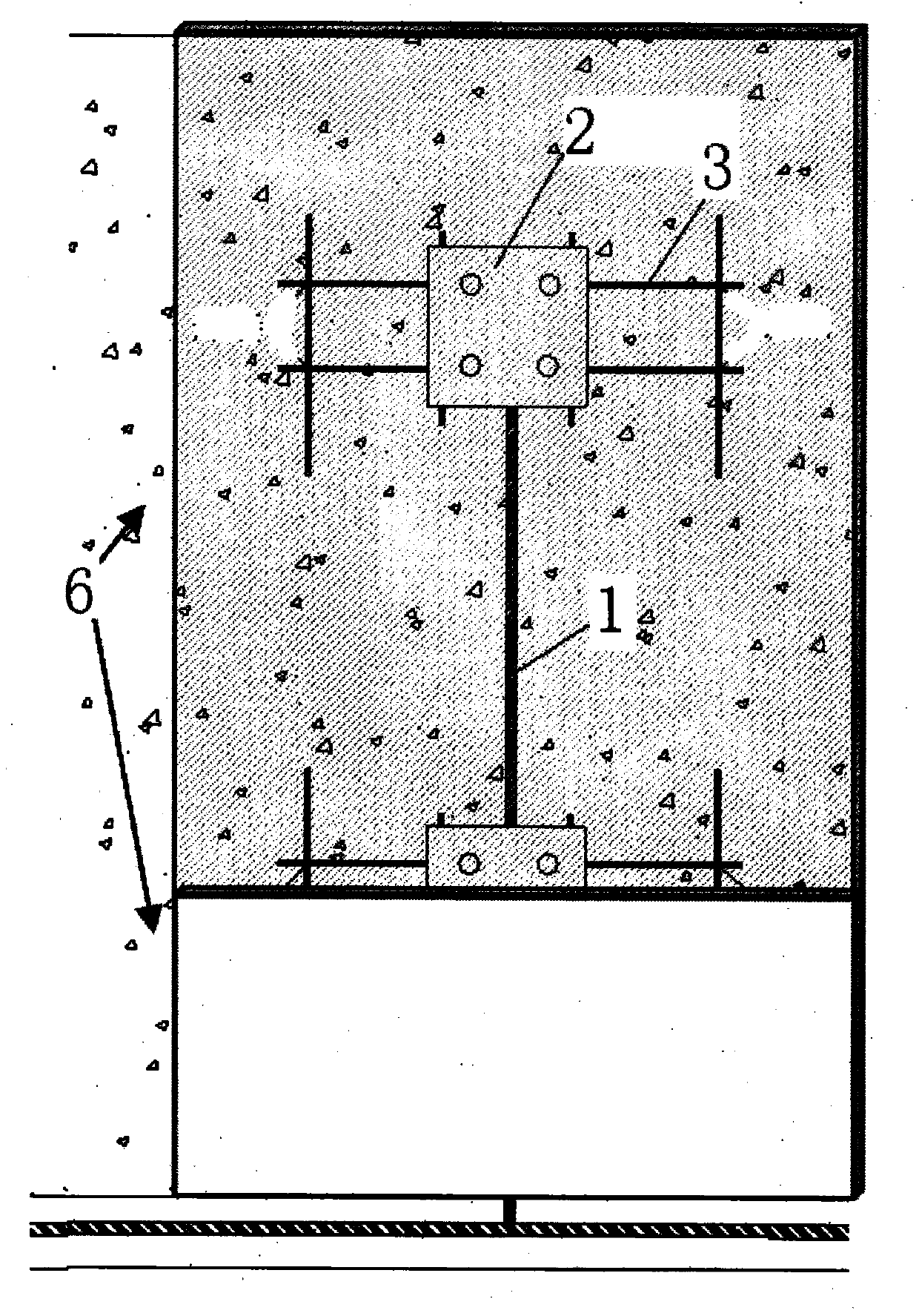
[0024] combine Figure 4 , a kind of wall ground plate installation method provided by the present invention, its steps are:

[0025] Step 1. Lay the grounding copper cable 1 after the wall reinforcement is bound, and weld the grounding copper cable 1 and the casting grounding plate 2 by exothermic welding;

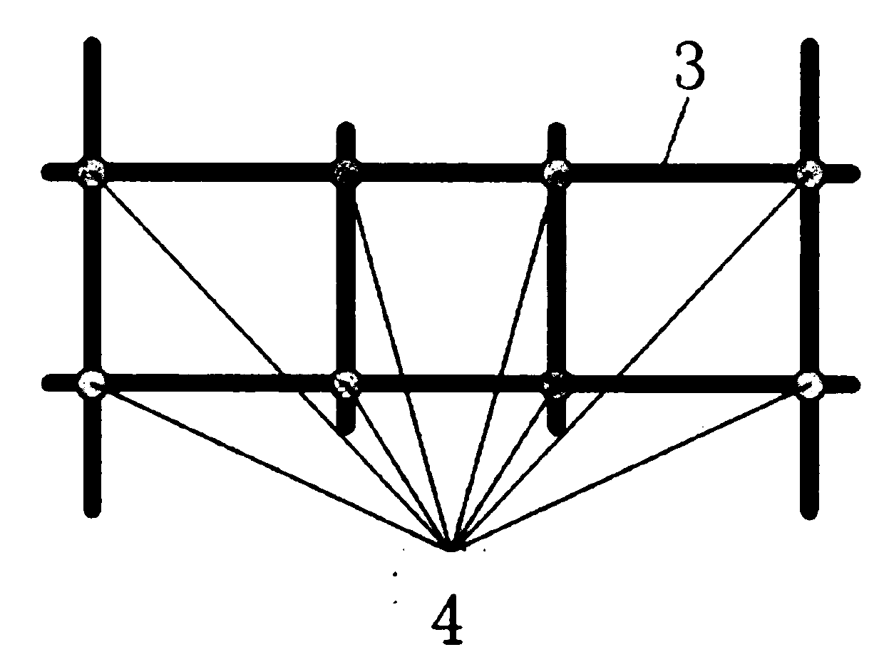
[0026] Step 2. According to the installation position of the casting grounding plate 2 on the drawing, mark a number of bolt holes of the casting grounding plate 2 at the corresponding positions of the formwork 6, determine the opening position, and open the formwork 6 at the determined opening position. The hole diameter is determined according to the diameter of the bolt matching the cast grounding plate 2;

[0027] Step 3. Screw the bolts that match the casting ground plate 2 into the holes opened in step 2. After passin...


PUM


Abstract

The invention provides an installation method for a concreted wall grounding plate. The installation method for the concreted wall grounding plate is characterized by comprising the following steps that the positions of bolt holes for the cast grounding plate are indicated in corresponding positions on a template according to diagram paper, the template is drilled in the determined positions, and the hole diameter is determined according to the diameter of bolts; the bolts matched with the grounding plate are screwed on the holes of the ground plate, after the bolts penetrate through the template, gaskets are arranged, then nuts are screwed on the bolts, and the cast grounding plate and the template are fixed tightly; the template is accurately positioned, split bolts are screwed up, and reinforcing rib plates are installed; after the template is detached, the bolts on the surface of the grounding plate are sealed through grease, and the situation that threads of the bolt holes are usable is guaranteed. The installation method for the concreted wall grounding plate improves the installation quality of the grounding plate, eliminates a fixing supporting system of an original installation method, saves the use amount of steel bars, reduces construction cost, and shortens the installation time of the grounding plate. The installation method for the concreted wall grounding plate is suitable for the building wall grounding plate installation projects of nuclear power, hydropower, thermal power, subways and urban building projects utilizing the bolt holt type cast grounding plates.

Description

technical field [0001] The invention relates to a building wall grounding plate installation project using a bolt hole type grounding plate in the fields of nuclear power, hydropower, thermal power, subway, urban construction engineering and the like. Background technique [0002] Such as figure 1 and figure 2 As shown, the current process of installing bolt-hole type casting grounding plates in concrete walls is as follows: First, lay the grounding copper cable 1 after the wall reinforcement is bound, and use exothermic welding to weld the grounding copper cable 1 and the casting grounding plate 2 . Then, the cast grounding plate 2 is fixed on the prefabricated welded steel support 3 . Reinforcement welded support 3 is different according to installation location, has such as Figure 3A and Figure 3B In the two forms shown, there are multiple welding points 4 on the steel bar welding bracket 3 . Subsequently, the steel bar welding bracket 3 is fixed on the main bar ...

Claims


Application Information

Patent Timeline
Patent Type & Authority Applications(China)
IPC IPC(8): E04G21/00E04G21/14H01R4/66
Inventor 李庆兴
Owner SHANGHAI NUCLEAR ENG RES & DESIGN INST CO LTD
Features
  • R&D
  • Intellectual Property
  • Life Sciences
  • Materials
  • Tech Scout
  • Unparalleled Data Quality
  • Higher Quality Content
  • 60% Fewer Hallucinations
Learn More