Refraction-amplifying optical displacement sensor

A technology of displacement sensor and optics, which is applied in the direction of using optical devices, instruments, measuring devices, etc., and can solve the problems of reducing measurement accuracy

Inactive Publication Date: 2013-12-11
CHANGCHUN UNIV OF SCI & TECH
View PDF5 Cites 18 Cited by
  • Summary
  • Abstract
  • Description
  • Claims
  • Application Information

AI Technical Summary

Problems solved by technology

Although the measurement device does not use a high-resolution PSD, but a normal resolution PSD, the measurement accuracy is still high
However, in this scheme, the micro-force elastic element and the moving plane mirror are connected by a connecting rod. It can be seen t

Method used


Image

  • Refraction-amplifying optical displacement sensor
  • Refraction-amplifying optical displacement sensor
  • Refraction-amplifying optical displacement sensor

Examples


Embodiment Construction

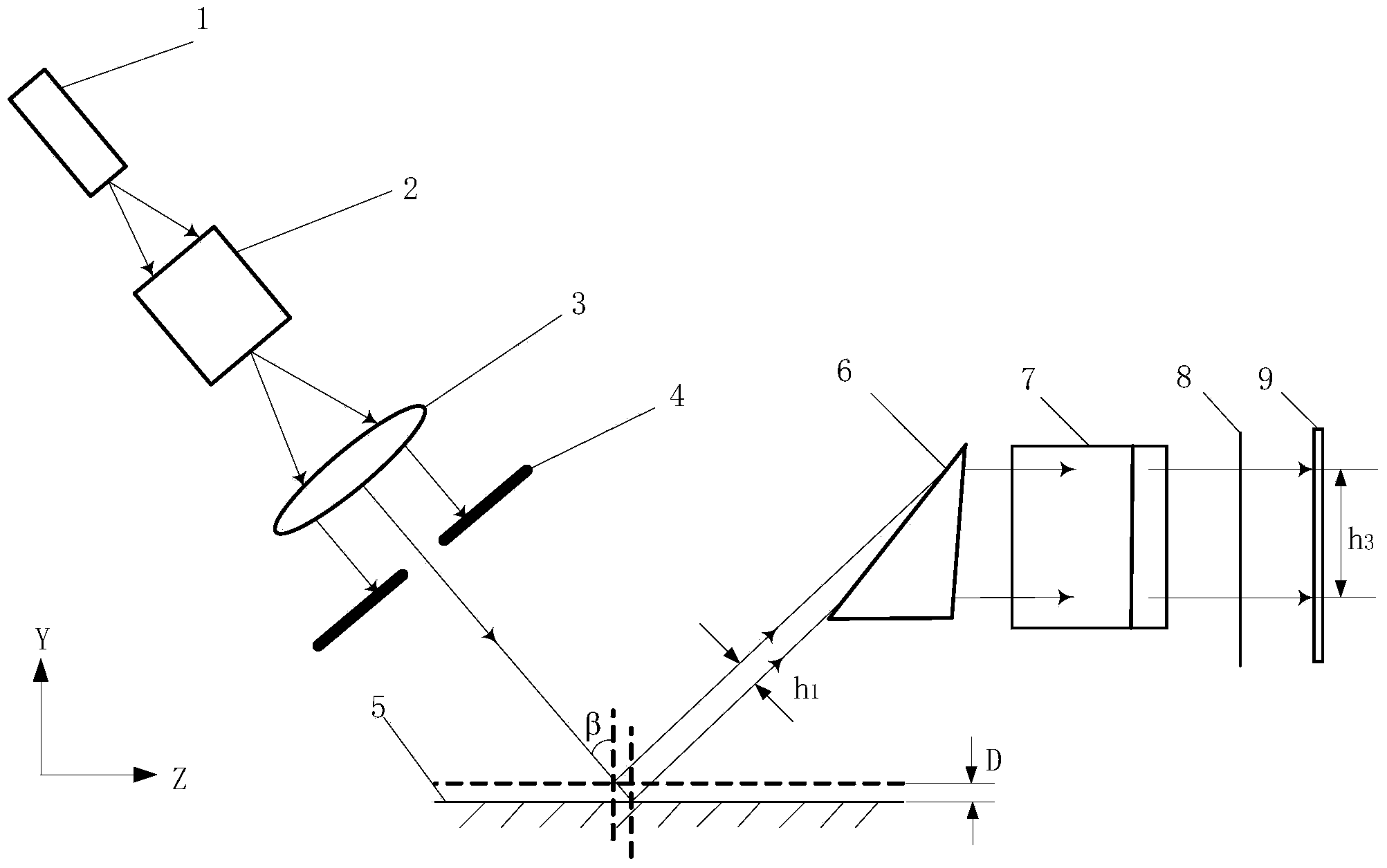
[0010] Laser light source 1 and PSD9 are arranged in the refraction amplification optical displacement sensor of the present invention, as figure 1 , figure 2 shown. After the laser light source 1 and before the refracting magnifying prism 6, a pinhole filter 2, a collimating lens 3, and an aperture stop 4 are sequentially arranged coaxially. The interference of dust in the air, optical elements in the laser light source 1 and scattered light of the measurement light itself on the measurement light is eliminated by the pinhole filter 2 . The collimating lens 3 makes the measurement light have a predetermined angle relative to the axis of the optical path, and becomes collimated light meeting requirements. Stray light is filtered out by the aperture diaphragm 4 and the beam diameter of the measuring light is reduced. The measurement light at this time is irradiated onto the surface 5 of the micro-force elastic element and reflected. The refracting magnifying prism 6 is loc...


PUM


Abstract

The invention belongs to the technical field of optical displacement measurement and relates to a refraction-amplifying optical displacement sensor. In the prior art, a micro-force elastic element and a movable plane mirror are connected through a connecting rod, and the contact type measurement is low in measuring accuracy. The refraction-amplifying optical displacement sensor comprises a laser light source and a PSD, a refraction amplifying triple prism is arranged between the laser light source and the PSD, the optical axis of the laser light source is spatially perpendicular to the axis of the refraction amplifying triple prism, the incidence angle a for measuring light emitted by the laser light source to irradiate into the refraction amplifying triple prism is larger than or equal to 70 degrees and smaller than 90 degrees, and a light sensing face of the PSD is perpendicular to the measuring light emitted from the refraction amplifying triple prism. The displacement D to be tested is amplified a plurality of times by the refraction amplifying triple prism, so that the requirements for the resolution ratio of the PSD are obviously reduced, and the ordinary resolution ratio can meet the requirements. In a measuring process, the refraction-amplifying optical displacement sensor is not in contact with the surface of the micro-force elastic element to be tested, so that the reduction of the measuring accuracy caused by mechanical connection is avoided.

Description

technical field [0001] The invention relates to a refraction amplified optical displacement sensor, which obtains the displacement value by amplifying the tiny displacement through optical refraction, and realizes the high-precision measurement of the micro-nano displacement. , The refraction amplification optical displacement sensor of the present invention has the characteristics of low price while realizing high-precision measurement, and belongs to the technical field of optical displacement measurement. technical background [0002] Due to the miniaturization of mechanical products and components, micro-electromechanical systems (MEMS) are required to be small in size. By studying the mechanical properties and motion characteristics of these micro-mechanisms, it can provide a basis for manufacturing excellent MEMS. Among them, it is particularly important to understand the friction and wear characteristics of MEMS. The existing technology uses micro-force elastic elemen...

Claims


Application Information

Patent Timeline
IPC IPC(8): G01B11/02
Inventor 于占江吴雅博于化东许金凯丁戗杨英歌
Owner CHANGCHUN UNIV OF SCI & TECH
Why Eureka
Try Eureka