Optical fiber conduction type rotor flow sensor

A rotor flow and sensor technology, applied in the field of optical fiber conduction rotor flow sensor, can solve the problem of inability to realize accurate instantaneous flow measurement and remote automatic adjustment of upper and lower limit positions, magnetic limit switches, magnetic field limit accuracy, and failure to meet the use requirements and other issues, to achieve the effects of long-distance transmission, manufacturing, and increasing manufacturing costs

Inactive Publication Date: 2013-12-11
SHANDONG UNIV
View PDF4 Cites 4 Cited by
  • Summary
  • Abstract
  • Description
  • Claims
  • Application Information

AI Technical Summary

Problems solved by technology

[0003] Patent 200620046512.2 discloses a fiber optic float flowmeter, which is equivalent to installing two photoelectric limit switches on the rotameter (installed at the upper and lower limits of the corresponding control flow), and the function is the same as that of conventional magnetic limit switches. The function of the switch is the same, it can only control the upper and lower limits of the flow rate (that is, output the control signal after the flow rate reaches the limit value), the problem it solves is as described in the technical background and the content of the invention, mainly to eliminate the magnetic field of the magnetic limit switch The influence of the influence and the problem of low limit accuracy, it cannot realize the continuous accurate measurement of the instantaneous flow rate and the remote automatic adjustment of the upper and lower limit positions (because it must be adjusted manually), and the optical signal controller is a one-to-one correspondence method , and its structure cannot be used in an array of a large number of sensitive elements (because a large number of solid-state lasers cannot be used as light sources, and one-to-one corresponding optical fibers are used as light sources, the output is very small and cannot meet the requirements of use)

Method used


Image

  • Optical fiber conduction type rotor flow sensor
  • Optical fiber conduction type rotor flow sensor
  • Optical fiber conduction type rotor flow sensor

Examples


Embodiment Construction

[0030] The present invention will be further described below in conjunction with the accompanying drawings.

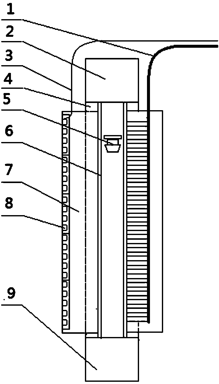
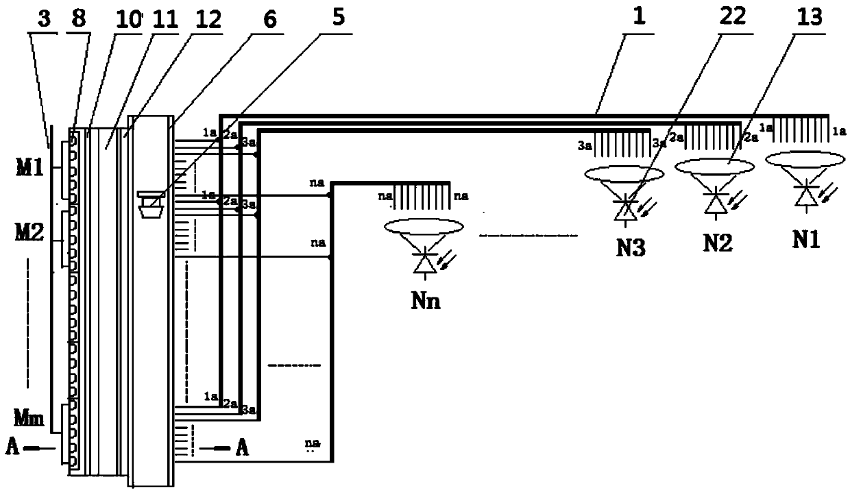
[0031] An optical fiber conduction rotor flow sensor, including a circuit system, a parallel light source, a glass rotor flowmeter, an optical fiber image transmission bundle 1 and a photodiode array, wherein,

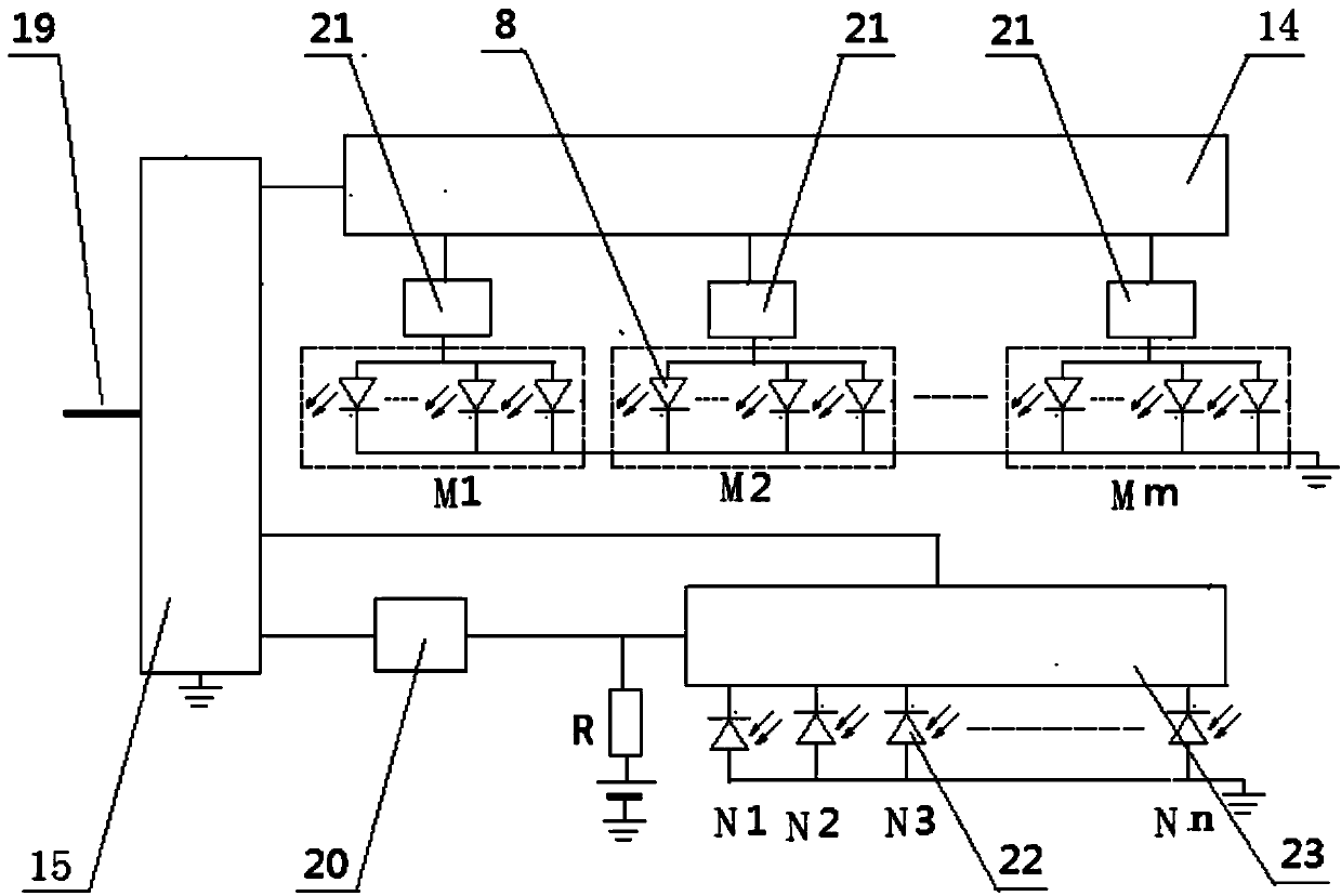
[0032] The structure of described circuit system is: comprise microprocessor 15, light source scanning circuit 14, drive circuit 21, signal processing circuit 20 and photosensitive diode scanning circuit 23, wherein, microprocessor 15 is connected with light source scanning circuit 14, light source scanning circuit 14 is connected to the LED8 through the drive circuit 21 (the drive circuit 21 is connected to the LED8 through the wire 3) (the LED8 in the LED array can be controlled to turn on and emit light sequentially through the light source scanning circuit 14); the microprocessor 15 is connected to the signal processing circuit 20, and the signal The proces...


PUM


Abstract

The invention discloses an optical fiber conduction type rotor flow sensor. The optical fiber conduction type rotor flow sensor comprises a circuit system, a parallel light source, a glass rotor flow meter, optical fiber coherent fiber bundles and a photosensitive diode array, wherein the optical fiber coherent fiber bundles are arrayed into an ordered vertical row in the axis direction of a glass tube and is contacted with the outer wall of the glass tube; the parallel light source and the optical fiber coherent fiber bundle array are located on the two sides of the glass tube; an optical fiber coherent fiber bundle array is located on the opposite side of the parallel light source; the length of the parallel light source is the same as that of the optical fiber coherent fiber bundle array; the optical fiber coherent fiber bundle array is composed of a vertical row of optical fibers; the row of the optical fibers is divided into m/2 groups; the arraying length of each group of the optical fibers is two times as much as the length of a floater; each group of the optical fibers is composed of n optical fibers and n is a positive integer; correspondingly, the photosensitive diode array is composed of n photosensitive diodes. The sensor disclosed by the invention has the following characteristics that a digital signal is output, the anti-jamming capability is strong, the resolution ratio is high, the performance is stable and reliable, the structure is simple and the cost is low.

Description

technical field [0001] The invention relates to an optical fiber conduction rotor flow sensor. Background technique [0002] Sensor technology has always been a popular technology, among which flow sensors are widely used in industrial production, chemical industry, environmental monitoring, biochemical technology and scientific experiments. Among the traditional flowmeters, the glass rotameter is a common category. Although the flowmeter has a simple structure and is easy to use, it can only meet the needs of on-site instant measurement, and cannot realize the recording and automatic control of the flow. In some existing rotor-type flow sensors, the conversion of physical quantities is mostly carried out in the form of analog quantity conversion (such as differential transformers). ), it is difficult to resist external interference, internal drift, stability and reliability are difficult to meet the requirements of use. The reliability and stability of digital sampling se...

Claims


Application Information

Patent Timeline
Patent Type & Authority Applications(China)
IPC IPC(8): G01F1/52
Inventor 孙晓明吴明海徐建强魏欣冰刘克敬
Owner SHANDONG UNIV
Why Eureka
Try Eureka