Device and method for automatically revising focal plane position of collimator

A collimator and calibration technology, applied in the field of optics, can solve the problems of heavy workload, low efficiency, and low calibration accuracy, and achieve the effects of increasing confidence, good repeatability, and improving calibration accuracy

Inactive Publication Date: 2013-12-11
XI'AN INST OF OPTICS & FINE MECHANICS - CHINESE ACAD OF SCI
View PDF5 Cites 9 Cited by
  • Summary
  • Abstract
  • Description
  • Claims
  • Application Information

AI Technical Summary

Problems solved by technology

Therefore, the pentagonal prism method using manual aiming and interpret

Method used


Image

  • Device and method for automatically revising focal plane position of collimator

Examples


Embodiment Construction

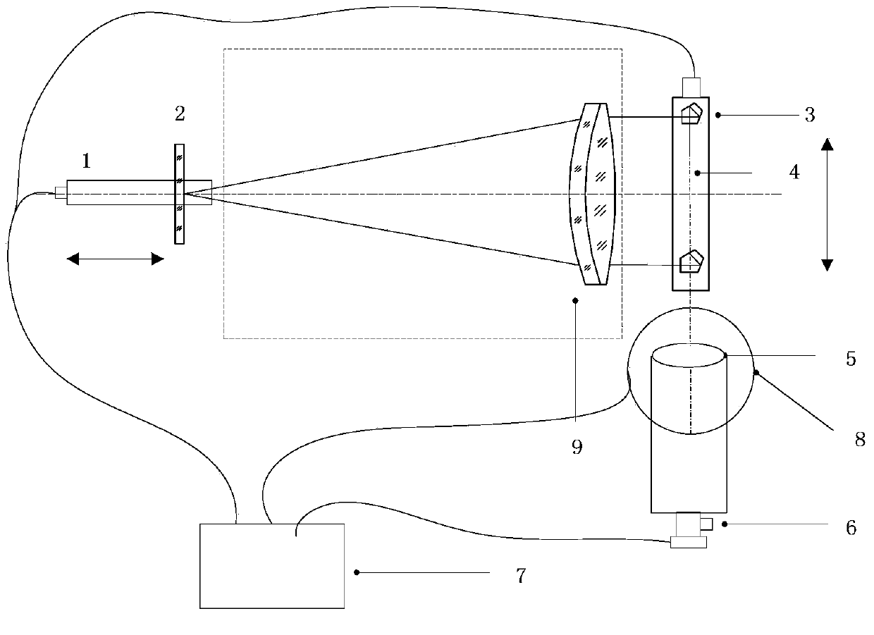
[0027] see figure 1 , the present invention provides an automatic calibration device for the focal plane position of a collimator, which device includes a standard collimation objective lens 5, a reticle 2, a pentagonal prism 3, a CCD image acquisition device 6, a high-precision image plane translation stage 1, The pentaprism scanning translation platform 4, the main control computer 7 and the precision turntable 8 are composed.

[0028] The tested collimator 9 is set between the reticle 2 and the pentagonal prism 3; the pentagonal prism 3 is set at the light outlet of the tested collimator 9; ; Main computer 7 respectively controls the reticle 2, the movement of the pentagonal prism 3 and the image acquisition of the aiming system.

[0029] In order to facilitate the precise control of the main control computer 7 on the reticle 2, the pentagonal prism 3 and the aiming system, the collimator focal plane position automatic calibration device provided by the present invention a...


PUM


Abstract

The invention relates to a device and method for automatically revising the focal plane position of a collimator. The device comprises a dividing plate, a pentagonal prism, an aim-taking system and a main control computer. A to-be-tested collimator is arranged between the dividing plate and the pentagonal prism. The pentagonal prism is arranged at a light outlet of the to-be-tested collimator. The aim-taking device is arranged on an light outgoing path formed by turning a light path through the pentagonal prism. The main control computer respectively controls the dividing plate and the pentagonal prism to move and controls image and data collection by the aim-taking system. The device and method for automatically revising the focal plane position of the collimator are high in revising efficiency and small in number of judging errors.

Description

technical field [0001] The invention belongs to the field of optics, and relates to an automatic calibration device and a calibration method for the focal plane position of a collimator, in particular to calibration of the focal plane position of a large-diameter collimator, evaluation of beam collimation and its focal length Measuring devices and methods. Background technique [0002] At present, in the calibration process of large-diameter collimators, the pentagonal prism method is widely used. In this method, the pentagonal prism scans within the clear aperture of the collimator, and when the collimator is focused, the longitudinal position of the reticle The error becomes the movement amount of the lateral position of the observed reticle image, so as to obtain the parallelism data of the beam of the collimator, and use it to determine the focal plane position of the collimator. [0003] The method of measuring the lateral position movement of the reticle image is usua...

Claims


Application Information

Patent Timeline
IPC IPC(8): G01M11/02
Inventor 李坤陈永权赵建科段亚轩龙江波薛璐
Owner XI'AN INST OF OPTICS & FINE MECHANICS - CHINESE ACAD OF SCI
Why Eureka
Try Eureka