Laser swept source with controlled mode locking for OCT medical imaging

A frequency-sweeping source and laser source technology, applied in lasers, medical science, semiconductor lasers, etc., can solve problems such as complexity and dispersion stability

Inactive Publication Date: 2013-12-11
EXCELITAS TECH
View PDF6 Cites 7 Cited by
  • Summary
  • Abstract
  • Description
  • Claims
  • Application Information

AI Technical Summary

Problems solved by technology

However, the disadvantage of these devices is their complexity
Additionally, ring resonators that include longer storage fibers create their own unique performance issues, such as dispersion and stability

Method used


Image

  • Laser swept source with controlled mode locking for OCT medical imaging
  • Laser swept source with controlled mode locking for OCT medical imaging
  • Laser swept source with controlled mode locking for OCT medical imaging

Examples


Embodiment Construction

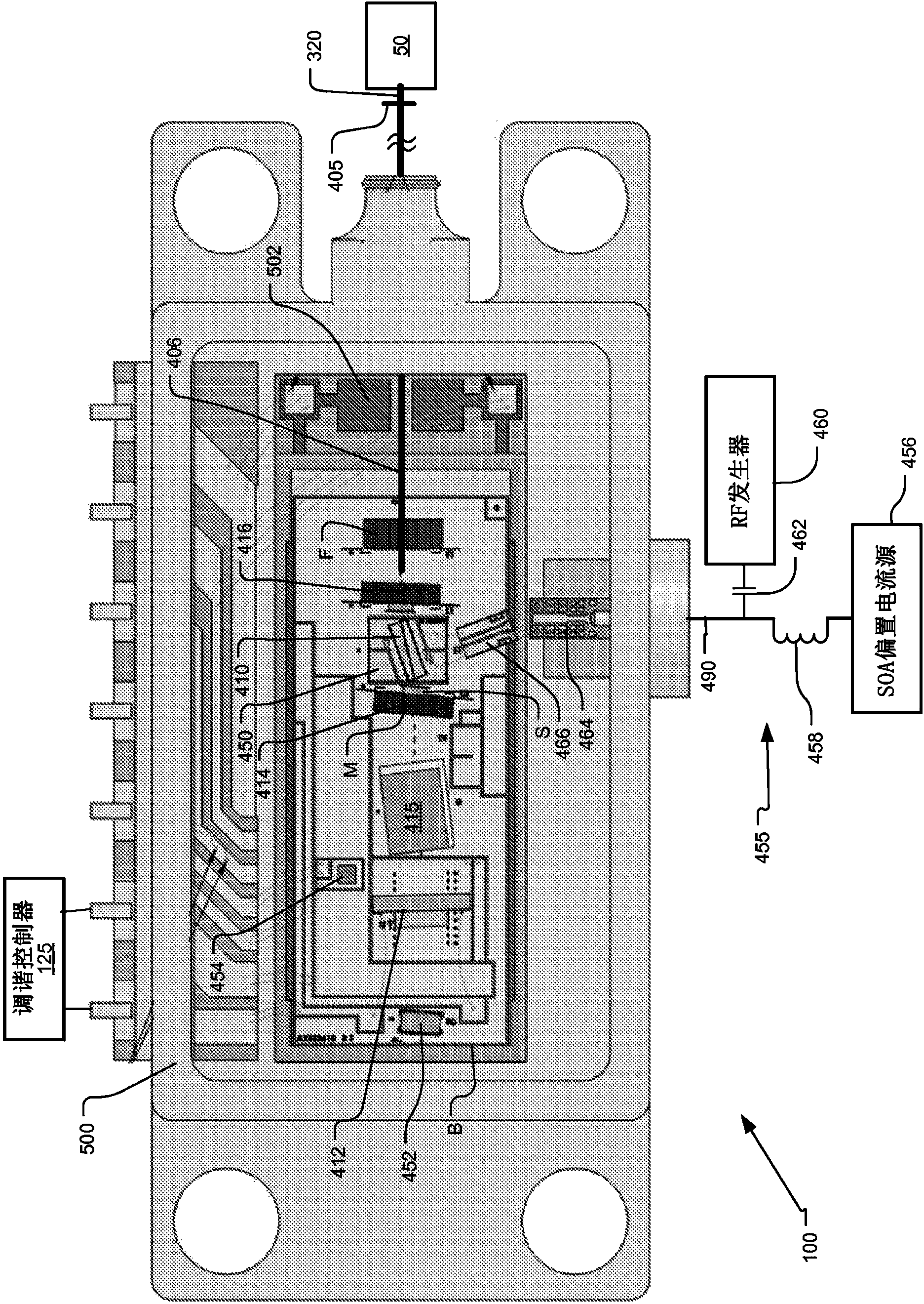
[0046] figure 1 Shown is a mode-locked laser swept source 100 for optical coherence analysis constructed in accordance with the principles of the present invention. This embodiment controls or stabilizes the mode-locked operation by modulating the bias current to the intracavity gain block.

[0047] In the current embodiment, preferably the swept laser source 100 is a laser generally described in US Pat. No. 7,415,049 B1. It comprises a linear resonant cavity with a gain component 410 and a frequency tuning component 412 . In the example shown, the frequency tuning component is a Fabry-Perot filter which, in the implementation shown, defines one end of the resonant cavity.

[0048] Other resonator structures are used in other embodiments, such as ring resonators. Further other cavity tuning elements are used, such as gratings and thin film filters. These elements can also be located entirely inside the resonator, such as angle isolated Fabry-Perot tunable filters or gratin...


PUM


Abstract

An optical coherence analysis system uses a laser swept source that is constrained to operate in a mode locked condition, which is accomplished by synchronously changing the gain and / or phase of a laser cavity based on the round trip travel time of light in the cavity. A plurality of high-speed wavelength swept laser sources emit pulses synchronized with the round trip time of the cavity as part of a nonlinear optical frequency red shifting process. Stable pulsation is associated with smooth tuning and low relative intensity noise. Addition of mode-locking methods to the class of lasers can control and stabilize the lasers to a low clock jitter and RIN state, and in specific cases allow long-to-short wavelength tuning in addition to the usual short-to-long (red shifting). The laser may comprise a SOA (410), a tunable Fabry-Perot -filter (412) as one reflector and an output coupler (405) in an optical fiber (406) to adjust the cavity length.

Description

[0001] related application [0002] This application claims priority to US Patent Application No. 12 / 979,225, filed December 27, 2010, which is hereby incorporated by reference in its entirety. Background technique [0003] Optical coherence analysis relies on the use of interference phenomena between a reference wave and an experimental wave, or between two parts of an experimental wave, for measuring distance and thickness, and for calculating the refractive index of a sample. Optical coherence tomography (OCT) is one example technique for performing high-resolution cross-sectional imaging. It is often used, for example, in real-time imaging of biological tissue structures at high magnification. Light waves reflect off an object or sample, and a computer uses information about how the waves change when reflected to create cross-sectional images of the object. [0004] Fourier domain OCT (FD-OCT) currently provides the best results for many applications. Furthermore, in a ...

Claims


Application Information

Patent Timeline
Patent Type & Authority Applications(China)
IPC IPC(8): H01S5/062H01S5/14H01S5/065H01S3/067H01S3/094H01S3/106H01S5/026H01S3/098
CPCA61B5/0066A61B5/6852G01N21/4795H01S3/06791H01S3/083H01S3/094026H01S3/1062H01S3/1109H01S3/1118H01S5/0265H01S5/041H01S5/06216H01S5/0622H01S5/0657H01S5/141H01S5/146G01B9/02004G01B9/02091H01S5/02251
Inventor B·C·约翰逊D·C·弗朗德斯
Owner EXCELITAS TECH
Why Eureka
Try Eureka