Device and method for monitoring microcirculation imaging

A monitoring device and imaging technology, applied in diagnostic recording/measurement, medical science, sensors, etc., can solve problems such as inability to observe areas of interest, limitations in transmission depth, and inability to observe

Active Publication Date: 2013-12-18
GUANGZHOU MEDSOFT SYST LTD
View PDF7 Cites 31 Cited by
  • Summary
  • Abstract
  • Description
  • Claims
  • Application Information

AI Technical Summary

Problems solved by technology

However, the limitation of laser Doppler microcirculation imaging technology is that it only measures the average value of all blood vessel velocities in a specific volume of tissue, so it cannot reflect the difference of different microvascular blood flow velocities, that is, the difference of each microvascular blood flow velocity. Heterogeneity of microcirculation is an important parameter to judge the state of microcirculation
However, the current microcirculation imaging device based on orthogonal polarization imaging still has its limitations, which are mainly reflected in: on the one hand, the polarized light is projected onto the skin surface in the normal incidence mode, so that the transmission depth of the polarized light or the observed microvascular The depth is limited, and usually can only penetrate within 1 mm under the skin, while the microcirculation is in the deeper human tissue under the skin surface; on the other hand, the microcirculation imaging device has a fixed field of view and numerical aperture, so that This makes the device have a fixed field of view and image resolution, so even with electronic magnification processing, it is not possible to obtain a finer view of the region of interest
For example, an abnormal area of ​​microcirculation is found in the image, but there is no way to observe the area in more detail, and it is impossible to obtain more detailed information

Method used


Image

  • Device and method for monitoring microcirculation imaging
  • Device and method for monitoring microcirculation imaging
  • Device and method for monitoring microcirculation imaging

Examples


Embodiment Construction

[0035] The following will clearly and completely describe the technical solutions in the embodiments of the present invention with reference to the drawings in the embodiments of the present invention.

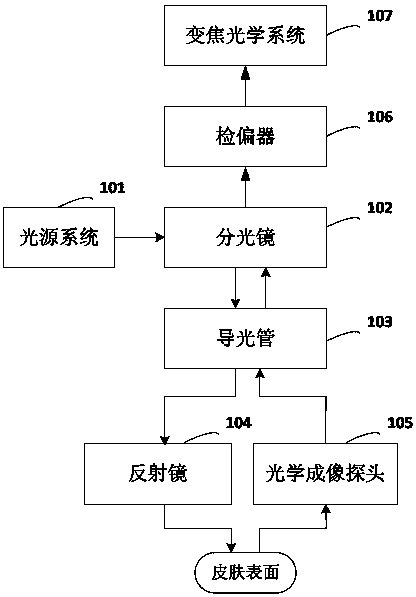
[0036] see figure 1 , is a structural block diagram of an embodiment of the microcirculation imaging monitoring device provided by the present invention.

[0037] In this embodiment, the microcirculation imaging monitoring device includes: a light source system 101 , a beam splitter 102 , a light pipe 103 , a mirror 104 , an optical imaging probe 105 , an analyzer 106 and a zoom optical system 107 .

[0038] The basic working principle of this microcirculation imaging monitoring device is: the light source system 101 emits polarized light whose polarization direction is parallel to the incident surface of the skin to the beam splitter 102; after the beam splitter 102 receives the incident polarized light, the incident polarized light passes through the guide The light pipe 10...


PUM


Abstract

The invention discloses a device for monitoring microcirculation imaging. The device comprises a light source system, a spectroscope, a light guide pipe, a reflecting mirror, an optical imaging probe, a polarization analyzer and a zoom optical system, wherein the light source system is used for supplying a polarized light of which a polarization direction is parallel to an incidence plane of a skin surface; the polarized light can reach to the reflecting mirror after being transmitted by the spectroscope and the light guide pipe; the reflecting mirror is used for adjusting an incidence angle of the polarized light projecting to the incidence plane of the skin surface; the optical imaging probe is used for collecting light rays which return to the skin surface after the scattering of a human tissue and transmitting the light rays to the polarization analyzer; the polarization analyzer is used for transmitting the light rays to the zoom optical system after filtering the light rays so as to collect images of the human tissue. According to the device provided by the invention, the transmission depth of the polarized light in the human tissue can be adjusted, a view field and a resolution ratio of the device can be adjusted in real time, and thus more meticulous observation to a specific area of the microcirculation imaging can be realized. The invention also discloses a method for monitoring the microcirculation imaging.

Description

technical field [0001] The invention relates to the technical field of biological optical imaging, in particular to a microcirculation imaging monitoring device and method. Background technique [0002] In the human blood circulation system, microcirculation refers to the blood circulation between arterioles and venules, which transports oxygen and nutrients to tissue cells and transports carbon dioxide CO 2 And the final link of metabolites is also the most important link. The perfusion of microcirculation is very important for cell metabolism, and microcirculation perfusion disturbance will cause serious metabolic disturbance, and severe cases will cause failure of various tissues and organs and lead to death. Real-time monitoring of the microcirculation status, especially how to quickly and simply monitor the microcirculation status of critically ill patients, such as early detection of signs of shock (microcirculatory failure), is crucial to improving the survival rate ...

Claims


Application Information

Patent Timeline
Patent Type & Authority Applications(China)
IPC IPC(8): A61B5/00
CPCA61B5/0075
Inventor 刘满林张莉均滕升亚历克斯·布兰多罗晓川
Owner GUANGZHOU MEDSOFT SYST LTD
Why Eureka
Try Eureka