Hydraulic control system for upper roll balancing device of rotary forging mill

A technology of hydraulic control system and balance device, which is applied in the direction of rolling mill control device, metal rolling, metal rolling, etc., can solve problems such as safety accidents, and achieve the effects of avoiding system pressure shock, overcoming internal leakage, and good sealing

Active Publication Date: 2013-12-18
TAIYUAN HEAVY IND
View PDF7 Cites 7 Cited by
  • Summary
  • Abstract
  • Description
  • Claims
  • Application Information

AI Technical Summary

Problems solved by technology

prone to safety accidents

Method used


Image

  • Hydraulic control system for upper roll balancing device of rotary forging mill
  • Hydraulic control system for upper roll balancing device of rotary forging mill
  • Hydraulic control system for upper roll balancing device of rotary forging mill

Examples


Embodiment Construction

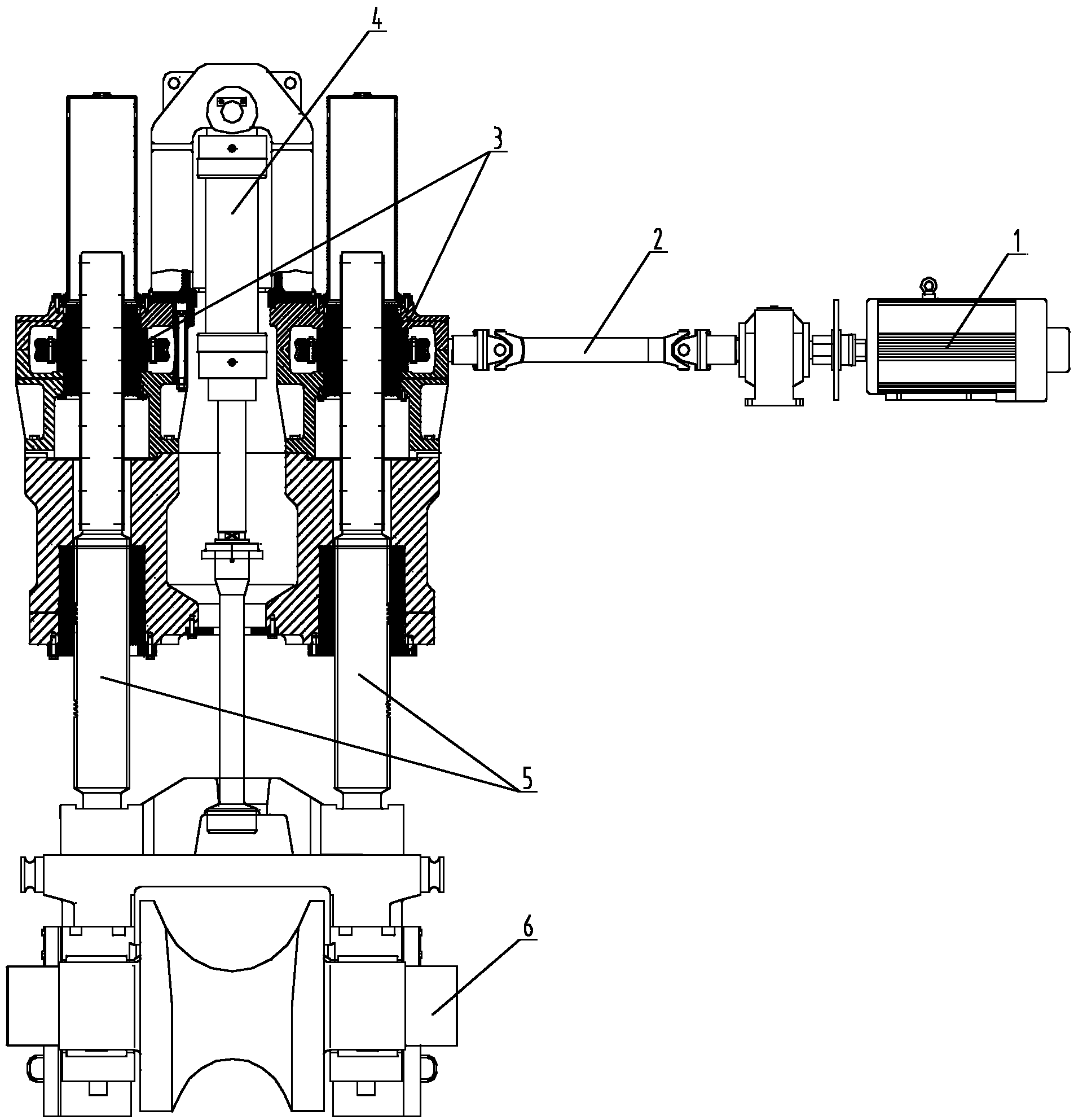
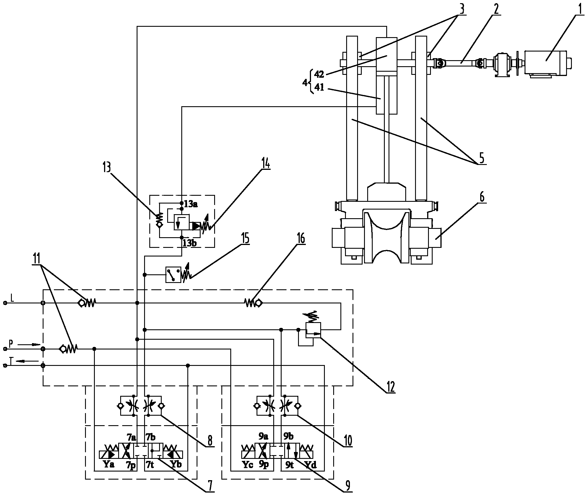
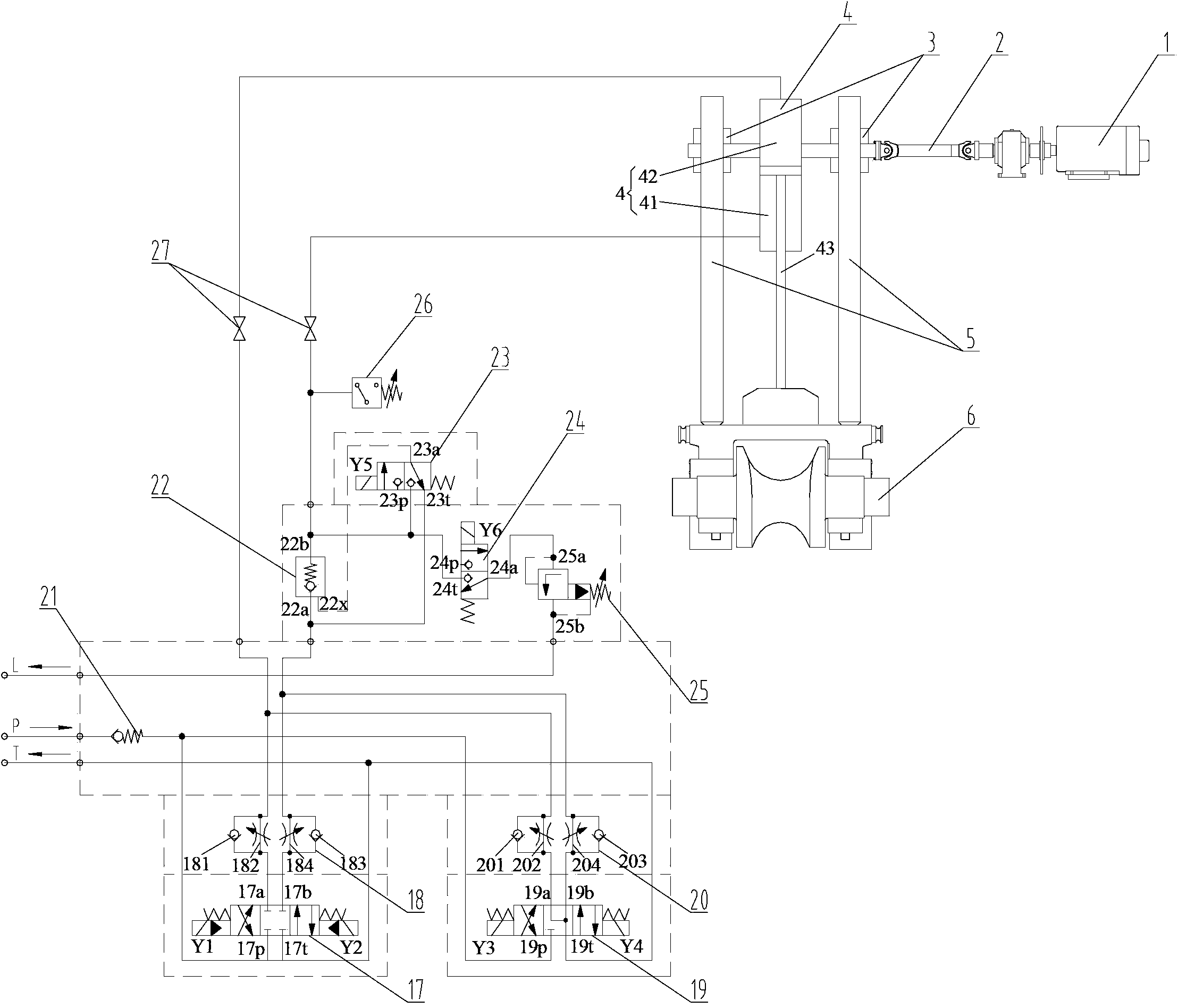
[0033] Such as image 3 As shown, an embodiment of the present invention proposes an upper roll balancing device for a periodic pipe rolling mill. The upper roll balancing device of the present invention includes a frequency conversion motor 1, a shaft coupling 2, a screw elevator 3, an upper roll balancing cylinder 4, a pressing Lead screw 5, upper roll box 6, its connection mode is the same as the connection mode of each part of existing upper roll balancing device, no longer repeat them here. In addition, the upper roll balancing device of the present invention also includes a hydraulic control system and a control device (not shown in the figure).

[0034] The hydraulic control system of the upper roll balancing device includes the system oil inlet P and the system oil inlet pipeline, the system oil return port T and the system oil return pipeline, the system oil drain port L and the system oil drain pipeline, and also includes the The first electro-hydraulic reversing va...


PUM


Abstract

The invention provides an upper roll balancing device and a hydraulic control system. The hydraulic control system comprises a system oil inlet, a system oil return port, a system oil drainage port, an upper roll balancing cylinder, a first electro-hydraulic directional valve, a second electro-hydraulic directional valve, a first one-way throttle valve, a second one-way throttle valve, a hydraulic control one-way valve, a first electromagnetic ball valve, a second electromagnetic ball valve and an overflow valve, wherein the first electro-hydraulic directional valve can be positioned at a left position, a middle position and a right position to control oil in the hydraulic control system to flow into a rod-including cavity and a rodless cavity of the upper roll balancing cylinder or be isolated from the rod-including cavity and the rodless cavity; the second electro-hydraulic directional valve can be positioned at a left position, a middle position and a right position to control oil in the hydraulic control system to flow into the rod-including cavity and the rodless cavity of the upper roll balancing cylinder or be communicated with the rod-including cavity and the rodless cavity; the hydraulic control one-way valve is communicated to the rod-including cavity through a pipeline; the first electromagnetic ball valve is connected in parallel to the hydraulic control one-way valve, and can be used for controlling the hydraulic control one-way valve to be opened; the second electromagnetic ball valve is communicated to the rod-including cavity through a pipeline, and is connected with the overflow valve; and the overflow valve is connected to the system oil drainage port.

Description

technical field [0001] The invention relates to an upper roll balance device of a periodic pipe rolling mill. In particular, it relates to a hydraulic control system of an upper roll balance device of a periodic pipe rolling mill. Background technique [0002] The periodic pipe rolling mill is an important equipment in the production of seamless steel pipes. The pass formed by the upper and lower rolls changes from large to small, so as to realize tube wall thinning and tube elongation. The adjustment of the pass shape of the periodic pipe mill is realized by controlling the rise or fall of the upper roll. [0003] figure 1 A schematic diagram of the upper roll balancing device is shown. Such as figure 1 As shown, the upper roll balancing device includes a frequency conversion motor 1, a shaft coupling 2, a screw jack 3, an upper roll balancing cylinder 4, a screw screw 5, and an upper roll box 6. The variable frequency motor 1 realizes the lifting or lowering of the l...

Claims


Application Information

Patent Timeline
Patent Type & Authority Applications(China)
IPC IPC(8): B21B37/78
Inventor 姜浩志
Owner TAIYUAN HEAVY IND
Why Eureka
Try Eureka